EDI High-Purity Water Equipment Installation: Complete Guide to Electrodeionization System Setup 2026
Installing an EDI high-purity water system correctly is critical for achieving the water quality your application demands. Electrodeionization (EDI) technology represents a revolutionary advance in ultrapure water production, combining ion exchange membranes, resin, and electrochemical principles to produce high-purity water continuously without chemical regeneration. This comprehensive guide covers EDI system installation procedures, working principles, key specifications, and operational best practices. Updated with 2026 industry standards.
* Last Updated: May 2026 | Industry-Verified Data
Why This Guide Matters
Electrodeionization (EDI) has become the preferred technology for producing high-purity water in the pharmaceutical, semiconductor, power generation, and laboratory industries. Since the industrialization of EDI membrane stack technology in 1986, thousands of systems have been installed worldwide, replacing traditional mixed bed ion exchange in the majority of new ultrapure water installations. The global EDI market was valued at approximately USD 1.2 billion in 2025 and is projected to reach USD 2.3 billion by 2034, driven by the semiconductor boom, pharmaceutical regulatory demands, and the increasing need for sustainable water treatment solutions that eliminate hazardous chemical handling. Proper installation is essential — a well-installed EDI system can operate for 15-20 years with minimal intervention, while installation errors can lead to premature membrane damage, poor water quality, and costly downtime.
Key Industry Trends (2026 Update)
- Pharmaceutical industry adoption accelerating: USP <1231> and EP water quality standards increasingly recommend EDI over mixed bed for purified water (PW) and water for injection (WFI) production, with over 60% of new pharmaceutical water systems now specifying EDI.
- Higher purity requirements in semiconductor manufacturing: The latest 3nm and 2nm chip fabrication processes require water resistivity above 18.2 MOhm-cm with TOC below 1 ppb — specifications that only properly designed and installed EDI-polished RO/EDI systems can consistently achieve.
- Smart EDI systems with predictive maintenance: Modern EDI modules incorporate embedded sensors for voltage, current, conductivity, temperature, and flow, enabling real-time performance monitoring and predictive maintenance scheduling that reduces unplanned downtime by 30-50%.
- Energy-efficient EDI module designs: New-generation EDI modules with optimized flow channel geometry and advanced ion exchange resin configurations reduce energy consumption by 20-35% compared to first-generation designs, achieving system power consumption as low as 0.05-0.15 kWh/m3 of product water.
1. How Does EDI Technology Work?
Fundamental Operating Principle
Electrodeionization (EDI) combines ion exchange membranes, ion exchange resin, and direct current electricity to continuously produce high-purity water without chemical regeneration. In the EDI module, alternating cation-permeable and anion-permeable membranes are arranged between a cathode and anode. The spaces between membranes are filled with mixed bed ion exchange resin, creating EDI units. Feed water enters these resin-filled compartments (dilute chambers), where the resin acts as a conductive medium, facilitating ion transport under the influence of the applied DC electric field. Ions migrate through the resin bed and across the selective membranes into adjacent concentrate chambers, where they are flushed to waste. The process continuously produces high-purity water from the dilute chamber outlets.
Key Components of an EDI System
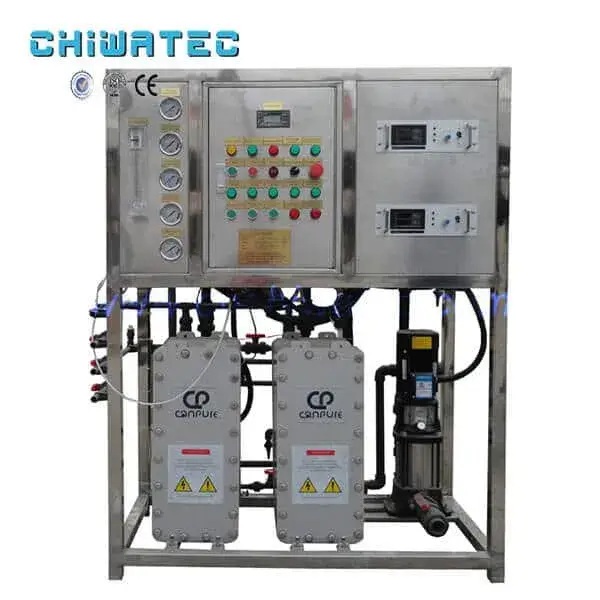
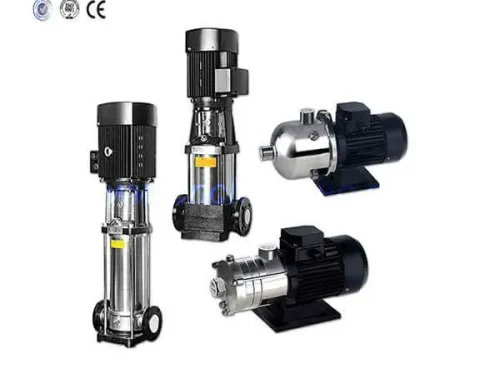
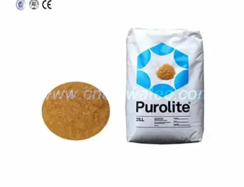
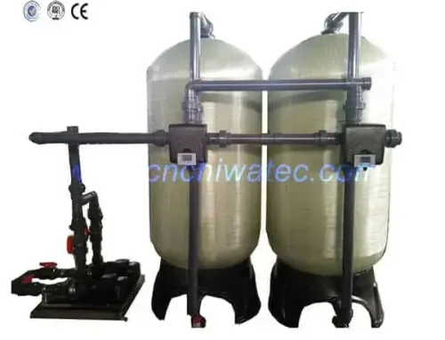
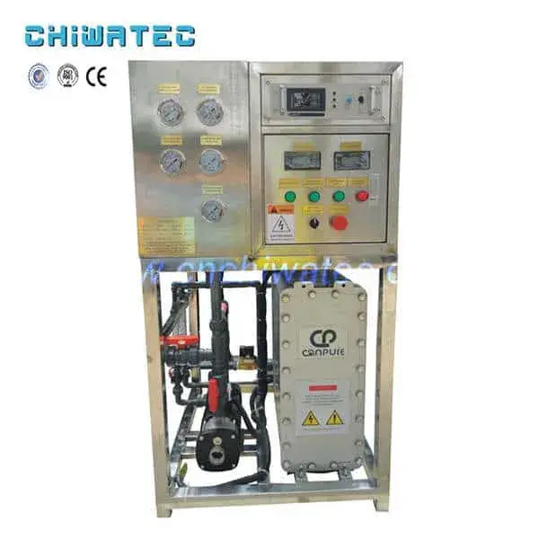
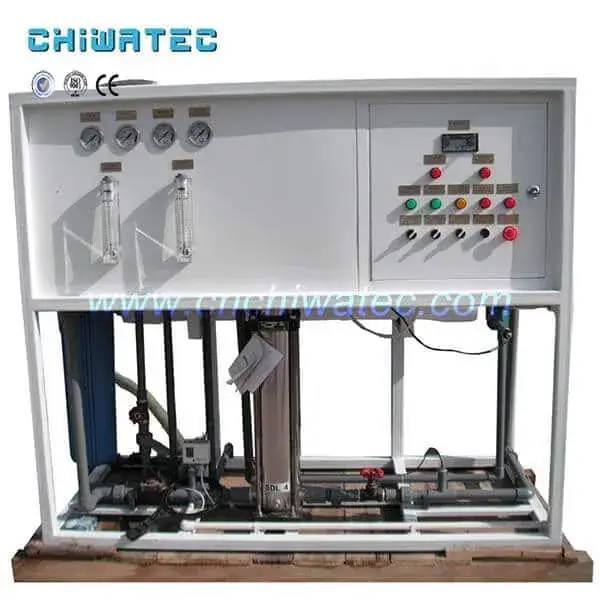
A complete EDI system includes: pre-treatment train — typically reverse osmosis (RO) producing feed water with conductivity below 20 microsiemens per centimeter; EDI module stack — the core component containing alternating ion-exchange membranes, resin-filled compartments, and electrode assemblies; DC power supply/rectifier — provides the electric field (typically 100-600 V DC) that drives ion migration; concentrate recirculation pump — maintains flow through concentrate chambers to prevent scaling; control system — monitors conductivity, flow, voltage, and current to maintain optimal operating conditions; and polishing loop — for the highest-purity applications, EDI product water may be further polished through a mixed bed or UV oxidation step.
For a comprehensive understanding of EDI fundamentals, see the EDI ultrapure water system working principle.
2. What Are the Critical Pre-Installation Requirements?
Feed Water Quality Specifications
EDI systems require high-quality feed water, typically from a reverse osmosis pre-treatment system. The critical feed water parameters specified by most EDI manufacturers include: conductivity — below 20 microsiemens per centimeter (ideally below 5 microsiemens per centimeter); total hardness — below 0.5 mg/L as CaCO3 to prevent scaling in the concentrate chambers; silica — below 0.5 mg/L to prevent irreversible fouling; TOC (total organic carbon) — below 0.5 mg/L; chlorine and other oxidizers — undetectable, as they will destroy ion exchange resin and membranes; carbon dioxide — below 5 mg/L, typically removed by degasification or membrane contactors; iron and manganese — below 0.01 mg/L; and turbidity — below 0.5 NTU. Failure to meet these feed water specifications is the most common cause of EDI system performance problems and premature module replacement.
Site Preparation Requirements
The installation site must provide: adequate floor space with load-bearing capacity for the system weight (typically 500-2000 kg depending on capacity); proper drainage for concentrate and electrode waste streams (pH-neutral, typically 10-30% of product flow rate); electrical supply matching the system requirements (typically 380-480 V, 3-phase for industrial systems); ambient temperature control between 5-40 degrees C; and adequate ventilation for heat dissipation from the power supply unit. The system should be installed on a level concrete floor with at least 1 meter clearance on all sides for maintenance access.
3. What Are the Step-by-Step Installation Procedures?
Mechanical Installation
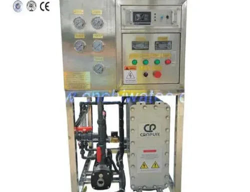
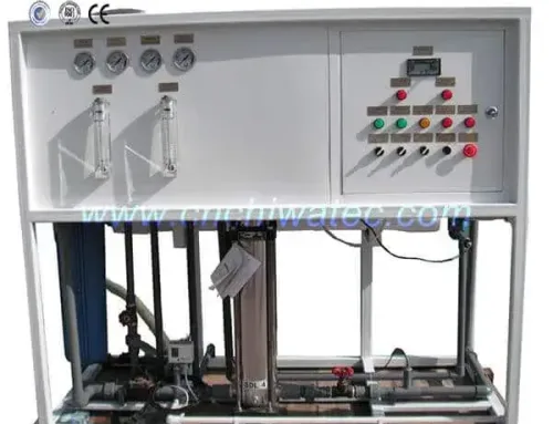
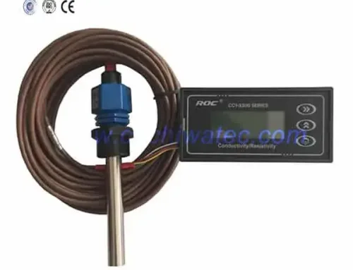
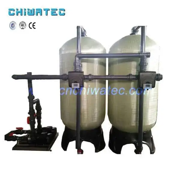
The mechanical installation of an EDI system follows these steps: positioning — place the EDI module frame and power supply cabinet on the prepared foundation, ensuring level alignment; piping connections — connect feed water inlet (typically 316 stainless steel or PVC), product water outlet, concentrate inlet/outlet, and electrode vent/outlet piping according to the system P&ID diagram; pre-treatment connection — connect the RO permeate line to the EDI feed inlet, ensuring all pre-treatment components (carbon filter, water softener, cartridge filter) are properly installed and operational; instrumentation — install conductivity sensors, flow meters, pressure gauges, and temperature sensors at specified locations; valve installation — install isolation valves, check valves, pressure relief valves, and flow control valves as specified in the system design.
Electrical Installation
The electrical installation includes: power supply connection — connect the DC rectifier/power supply to the EDI module electrodes, observing correct polarity (anode positive, cathode negative); control wiring — connect PLC or controller to sensors, valves, and pumps according to the wiring diagram; grounding — properly ground all electrical components per local electrical codes; safety interlocks — verify that low-flow, high-conductivity, and over-temperature interlocks are correctly wired and functional. For detailed electrical setup guidance, refer to the operating instructions for EDI equipment.
The features and process flow of EDI ultrapure water equipment provides additional information on system configuration and flow path design.
4. How to Commission an EDI System After Installation?
Initial Startup Procedure
Commissioning an EDI system requires systematic verification of all components before introducing power. The procedure includes: leak testing — pressurize all water circuits to 1.5 times the design pressure and check all connections for leaks; feed water quality verification — confirm that RO permeate quality meets EDI feed specifications (conductivity below 20 microsiemens per centimeter, hardness below 0.5 mg/L); flow rate adjustment — set feed, product, and concentrate flow rates to manufacturer specifications using the installed flow control valves and rotameters; pressure check — verify that inlet pressure is within the specified range (typically 4-7 bar) and that pressure differential across the module is within limits; electrical continuity check — verify proper wiring connections and insulation resistance before applying power.
Voltage Ramp-Up and Stabilization
Once mechanical and electrical checks are complete, the EDI module is energized. The DC voltage is applied gradually — typically starting at 25% of the design voltage and increasing in steps over 30-60 minutes while monitoring product water conductivity. As the voltage increases, the resin bed in the dilute chamber becomes polarized, and ions are driven across the membranes. Product water conductivity typically decreases from near-feed levels to below 1 microsiemens per centimeter within 1-4 hours of startup. The system reaches full steady-state performance after 24-72 hours of continuous operation, achieving product water resistivity of 10-18.2 MOhm-cm depending on feed quality and system design.
5. What Are the Key Differences Between EDI and Mixed Bed Technology?
Operational Comparison
EDI offers several significant advantages over traditional mixed bed ion exchange. Continuous operation — EDI produces high-purity water continuously without the need for periodic regeneration shutdowns, providing uninterrupted water supply. No chemical handling — EDI eliminates the need for hazardous acid and caustic chemicals required for mixed bed regeneration, improving operator safety and reducing regulatory compliance burden. Lower operating costs — EDI systems typically have 30-50% lower operating costs than mixed bed systems when considering chemical purchases, waste disposal, and labor. Smaller footprint — EDI systems occupy approximately 50-60% less floor space than equivalent mixed bed systems. Environmental benefits — EDI eliminates acid and caustic waste neutralization requirements, reducing environmental impact.
When Each Technology Is Preferred
Mixed bed technology remains advantageous in certain scenarios: very low flow rate applications (below 1 m3/h) where EDI module costs are difficult to justify; applications with intermittent operation where EDI modules may not maintain polarization; and situations where feed water conductivity is consistently above 50 microsiemens per centimeter, which exceeds most EDI module design limits. For high-purity water production above 1 m3/h with consistent operation, EDI is now the standard choice. For an in-depth comparison, see the EDI as a replacement for mixed bed technology and advantages of EDI technology compared with hybrid ion exchange.
6. What Are the Recommended Operating Parameters?
Standard Operating Conditions
Typical EDI system operating parameters include: product flow rate — 1-50 m3/h per module stack depending on module size (standard modules rated at 2-20 m3/h); recovery rate — 90-95% (5-10% of feed water goes to concentrate and electrode waste); operating voltage — 100-600 V DC depending on module design and feed water conductivity; operating current — 1-10 A per module stack; inlet pressure — 4-7 bar (60-100 psi); temperature range — 5-45 degrees C (optimal performance at 15-30 degrees C); product water resistivity — typically 10-18.2 MOhm-cm; silica removal — 99%+; TOC removal — 90-95%.
Impact of Operating Conditions on Performance
Product water quality varies with operating conditions. Higher voltage increases ion removal but excessive voltage can cause water splitting at the membrane surface, generating hydrogen and hydroxide ions that reduce product water resistivity. Higher feed water temperature increases ion mobility and improves performance but temperatures above 45 degrees C can damage membranes. Lower feed water conductivity improves product water quality but may require higher voltage to maintain current flow through the resin bed. Proper control system tuning is essential to maintain optimal voltage-current operating points as feed conditions vary.
7. How to Maintain an EDI System?
Routine Maintenance Procedures
EDI systems require relatively minimal maintenance compared to mixed bed systems. Daily checks — verify product water resistivity, flow rates, operating voltage and current, and inlet pressure. Weekly checks — inspect for leaks, check pre-treatment system performance (RO permeate quality), and record system operating data. Monthly checks — clean or replace pre-treatment cartridge filters; check chemical dosing systems (antiscalant, if used). Quarterly checks — perform a system performance assessment comparing current operating data to baseline values; inspect concentrate chamber for scaling; verify instrument calibration. Annual maintenance — inspect EDI module stack for signs of scaling or fouling; clean module if necessary using manufacturer-approved cleaning procedures; replace seals and O-rings as needed.
Common Issues and Troubleshooting
The most common EDI system problems include: increasing voltage requirements — indicating resin or membrane fouling, typically caused by hardness scaling or organic fouling; declining product water resistivity — caused by feed water quality excursions, membrane damage, or electrical issues; high pressure differential — indicating particulate fouling or flow restriction; and concentrate chamber scaling — caused by inadequate concentrate flow or high hardness in feed water. Comprehensive troubleshooting guidance for all common issues can be found in the EDI ultrapure water equipment problems and solutions and how to maintain EDI ultrapure water equipment.
8. What Are the Quality Standards for EDI Product Water?
Industry-Specific Water Quality Requirements
Different industries require different EDI product water quality specifications. For pharmaceutical applications, USP Purified Water requires conductivity below 1.3 microsiemens per centimeter at 25 degrees C, while USP Water for Injection (WFI) requires the same conductivity plus endotoxin limits below 0.25 EU/mL. For semiconductor manufacturing, ASTM D5127 Type E-1.2 ultrapure water requires resistivity above 18.0 MOhm-cm, TOC below 5 ppb, dissolved oxygen below 10 ppb, and particle counts below 100 particles per liter at 0.05 microns. For power generation, boiler feed water typically requires conductivity below 0.1 microsiemens per centimeter for high-pressure boilers.
Quality Monitoring and Documentation
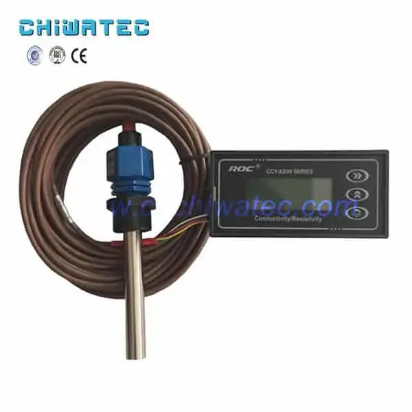
Continuous online monitoring of product water quality is essential for EDI systems. Key monitoring parameters include: resistivity/conductivity (online cell), TOC (online analyzer for critical applications), silica (online or grab sample), particle counts (for semiconductor applications), and bacteria counts (for pharmaceutical applications). Data logging and trending enable early detection of performance degradation and support regulatory compliance documentation. Most modern EDI systems include data acquisition software that generates automated reports for quality assurance records.
9. What Is the Expected Service Life of an EDI System?
Module Life and Replacement
EDI modules have a typical service life of 3-8 years, depending on feed water quality, operating conditions, and maintenance practices. Factors that extend module life include: consistently high-quality feed water (conductivity below 5 microsiemens per centimeter), stable operating conditions (avoiding frequent startups and shutdowns), proper chemical-free pre-treatment (RO + softening + carbon filtration), and regular performance monitoring with timely corrective action. Under optimal conditions, EDI module life can reach 10 years or more. Module replacement costs typically range from 30-50% of the original system cost, making proper operation and maintenance economically important.
System Component Life
Beyond the EDI module itself, other system components have varying service lives: DC power supply/rectifier — 10-15 years with proper ventilation and electrical maintenance; pumps — 8-12 years with regular seal replacement; instrumentation (conductivity cells, flow meters) — 5-10 years depending on calibration and cleaning practices; piping and valves — 15-20 years for stainless steel, 10-15 years for PVC/CPVC. Regular preventive maintenance is the single most important factor in maximizing the overall system service life. The ten advantages of EDI electric desalination systems provides additional detail on system durability and design life considerations.
10. What Are the Applications of EDI Technology Across Industries?
Pharmaceutical and Biotechnology
EDI is widely used in pharmaceutical water systems to produce USP Purified Water and, in combination with appropriate pre-treatment and post-treatment, Water for Injection (WFI). The pharmaceutical industry values EDI for its continuous operation, lack of chemical regeneration, and consistent product water quality that meets stringent regulatory requirements. EDI systems in pharmaceutical applications typically include comprehensive validation documentation, including IQ/OQ/PQ protocols.
Semiconductor and Microelectronics
The semiconductor industry is the most demanding user of EDI technology, requiring ultrapure water with resistivity above 18.2 MOhm-cm and TOC below 1 ppb for advanced node manufacturing. EDI serves as the final polishing step after RO in semiconductor ultrapure water systems, with the EDI product water further polished through UV oxidation, mixed bed ion exchange, and membrane degasification. As chip fabrication moves to 3nm and below, EDI system specifications continue to tighten.
Power Generation
Power plants use EDI to produce high-purity boiler feed water and for condensate polishing. EDI systems in power applications are typically larger (50-500 m3/h) and operate at higher temperatures than other applications. The elimination of chemical regeneration is particularly valuable in power plant environments where chemical handling and storage present safety and regulatory challenges.
Laboratory and Research
Laboratory EDI systems produce Type I (18.2 MOhm-cm) ultrapure water for analytical applications including HPLC, ICP-MS, cell culture, and molecular biology. These compact systems typically integrate RO pre-treatment, EDI polishing, UV oxidation, and final filtration into a single benchtop or floor-standing unit.
Conclusion
EDI high-purity water equipment represents a significant advancement over traditional mixed bed ion exchange technology, offering continuous operation, chemical-free regeneration, lower operating costs, and consistent product water quality. Proper installation — from feed water quality verification and site preparation through mechanical assembly, electrical connection, and systematic commissioning — is essential for achieving the water quality and system reliability that EDI technology can deliver. With proper operation and maintenance, EDI systems provide 15-20 years of reliable service, making them the technology of choice for pharmaceutical, semiconductor, power generation, and laboratory high-purity water applications worldwide.
For expert assistance in designing, installing, or maintaining an EDI high-purity water system for your specific application, contact CHIWATEC today at [email protected] or [email protected] or via WhatsApp at 008618292684865. CHIWATEC provides comprehensive water treatment solutions including design, machining, installation, commissioning, and customized one-stop service for EDI and ultrapure water systems worldwide.
Frequently Asked Questions
Q1: What is the difference between EDI and mixed bed ion exchange?
EDI operates continuously without chemical regeneration, using electricity to drive ion removal across ion-exchange membranes. Mixed bed requires periodic shutdown for chemical regeneration with acid and caustic. EDI eliminates chemical handling, reduces operating costs by 30-50%, and requires 50-60% less floor space, but requires higher-quality feed water (RO permeate with conductivity below 20 microsiemens per centimeter).
Q2: What feed water quality does an EDI system require?
EDI systems require RO permeate feed water meeting: conductivity below 20 microsiemens per centimeter (ideally below 5), total hardness below 0.5 mg/L as CaCO3, silica below 0.5 mg/L, TOC below 0.5 mg/L, undetectable chlorine/oxidizers, iron and manganese below 0.01 mg/L, and turbidity below 0.5 NTU. Meeting these specifications is essential for reliable EDI operation and module longevity.
Q3: How long does it take to commission an EDI system?
Initial startup and verification typically takes 4-8 hours, including leak testing, flow adjustment, and gradual voltage ramp-up. Product water conductivity typically drops below 1 microsiemens per centimeter within 1-4 hours. Full steady-state performance achieving target resistivity (10-18.2 MOhm-cm) is reached after 24-72 hours of continuous operation.
Q4: How often should an EDI module be replaced?
EDI modules typically last 3-8 years under normal operating conditions, with well-maintained systems in optimal feed water conditions achieving 8-10 years. Signs that replacement is needed include: increasing voltage requirements to maintain product quality, inability to achieve target resistivity, high pressure differential, or physical damage to the module housing.
Q5: Can EDI completely replace mixed bed ion exchange?
EDI has replaced mixed bed in most new ultrapure water installations above 1 m3/h capacity. However, mixed bed remains relevant for: very small systems (below 1 m3/h), intermittent operation applications, very high feed water conductivity (above 50 microsiemens per centimeter), and as a final polishing step after EDI in the most demanding semiconductor and pharmaceutical applications requiring the absolute highest water quality.
Related Resources and Further Reading
Do you have a water treatment project we can help with
* Designing,machining,installing,commissioning, customize and one-stop service