Reverse Osmosis Water Treatment System Design: Complete RO Equipment Program Guide 2026
Looking for a comprehensive RO water treatment equipment program description? A well-designed reverse osmosis system is the cornerstone of modern water purification, serving industries from electronics and pharmaceuticals to power generation and food processing. This guide provides a complete program description of RO water treatment equipment – covering system architecture, component specifications, water quality requirements, design calculations, and operational parameters. Whether you are designing a new RO system, evaluating equipment proposals, or optimizing existing installations, this resource delivers the technical depth needed for informed decision-making.
*Last Updated: May 2026 | Industry-Verified Data*
Why This Guide Matters
The global reverse osmosis membrane market was valued at approximately USD 8.5 billion in 2024 and is projected to reach USD 16.2 billion by 2034, growing at a CAGR of 6.7%. RO systems account for over 60% of the world’s desalination capacity and are increasingly adopted for industrial water purification, wastewater reuse, and drinking water treatment. A properly designed RO system can achieve 97-99% salt rejection, 75-85% water recovery, and reliable operation for 15-20 years with proper maintenance. Understanding the complete equipment program – from raw water intake to product water storage – is essential for successful RO system implementation.
Key Industry Trends (2026 Update)
- Energy Recovery Integration: Modern RO systems increasingly incorporate energy recovery devices (ERDs) such as pressure exchangers and turbochargers, reducing specific energy consumption by 30-60% compared to conventional systems, bringing it down to 2.5-3.5 kWh/m³ for seawater RO.
- AI-Driven Design Optimization: Computational fluid dynamics (CFD) and machine learning algorithms are now used to optimize membrane element configuration, feed spacer design, and system hydraulics, improving recovery rates by 5-10% while reducing fouling propensity.
- Smart Monitoring and Predictive Analytics: IoT-enabled RO systems with real-time normalized permeate flow, salt rejection, and pressure drop monitoring can predict membrane fouling 24-48 hours in advance, reducing unplanned downtime by 40-60%.
- Low-Energy Membrane Elements: New-generation thin-film composite (TFC) membranes operate at 20-30% lower feed pressure while maintaining 99%+ salt rejection, enabling significant energy savings (USD 0.02-0.05/m³) in brackish water RO applications.
1. What Are the Water Quality Requirements for RO System Feed Water?
Critical Feed Water Parameters
RO systems require specific feed water quality to ensure reliable operation and long membrane life. Key parameters include: Silt Density Index (SDI) below 5 (ideally below 3), measured as SDI-15 minutes; turbidity below 1.0 NTU; free chlorine below 0.1 ppm (chlorine damages polyamide RO membranes); temperature between 5-45 degrees C for standard membranes; pH between 2-11 (continuous operation), ideally 6-8; iron below 0.05 ppm; manganese below 0.05 ppm; hydrogen sulfide below 0.1 ppm; and TDS up to 45,000 ppm (seawater) or up to 10,000 ppm (brackish water).
Feed Water Analysis Requirements
Before designing an RO system, a complete feed water analysis is mandatory, including: major cations (Ca, Mg, Na, K, Fe, Mn, Ba, Sr), major anions (Cl, SO4, HCO3, CO3, NO3, F, SiO2), calculated parameters (TDS, hardness, alkalinity, Langelier Saturation Index), and physical parameters (temperature, pH, turbidity, SDI, TOC). Seasonal variations must be captured through quarterly sampling over at least one year for surface water sources.
2. What Is the Complete RO Water Treatment Equipment Program Flow?
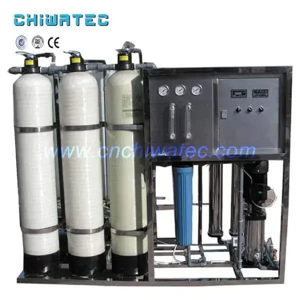
Standard RO System Process Flow
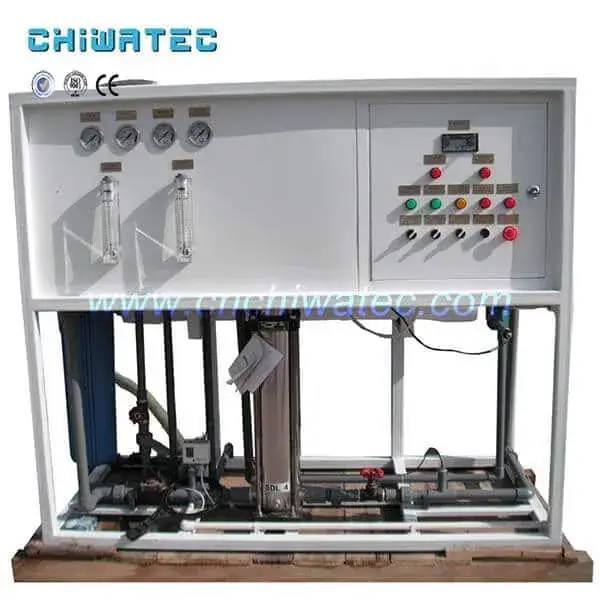
The typical RO water treatment equipment program follows this sequence: Raw water source → Raw water storage tank → Feed booster pump → Multi-media mechanical filter → Activated carbon filter → Water softener (or antiscalant dosing) → Cartridge precision filter (5 micron) → High-pressure pump → Reverse osmosis membrane array → Product water storage tank → Post-treatment (if required: UV, pH adjustment, remineralization). Each component serves a specific function in protecting the RO membranes and ensuring consistent product water quality.
Component Description and Function
- Raw water tank: Provides stable water supply, overcoming pipeline pressure fluctuations. Typical capacity: 2-4 hours of system feed flow. Equipped with level control, overflow, and drain.
- Feed booster pump: Provides necessary pressure (2-4 bar) for pretreatment equipment. Selected based on total dynamic head of pretreatment train plus 10-15% safety margin.
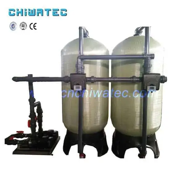
- Multi-media mechanical filter: Removes suspended solids down to 20-25 microns using graded layers of quartz sand, anthracite, and garnet. Equipped with automatic backwash based on time or pressure differential.
- Activated carbon filter: Adsorbs free chlorine and organic compounds that would damage polyamide RO membranes. Granular activated carbon (GAC) with iodine number above 900. Service life: 6-12 months between replacements.
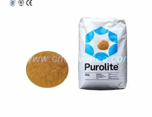
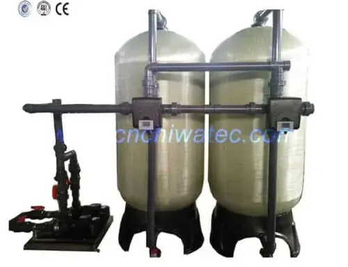
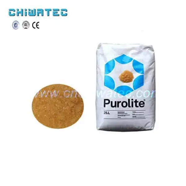
- Water softener or antiscalant dosing: Removes calcium and magnesium hardness to prevent membrane scaling. Alternatively, antiscalant dosing at 2-5 ppm controls scale formation without removing hardness. Selection depends on feed water hardness and recovery rate.
- Cartridge precision filter: Final 5-micron (or 1-micron) filtration before RO membranes to capture any particulates that could damage membrane elements. Housings are typically 7-30 cartridges of 20-40 inch length.
- High-pressure pump: Provides the operating pressure required for RO separation. For brackish water: 10-15 bar; for seawater: 50-70 bar. Typically multistage centrifugal or positive displacement for high-pressure applications.
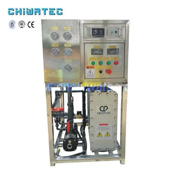
- RO membrane array: The core separation stage, typically configured in a tapered array (e.g., 2:1 or 4:2:1) to maintain optimal cross-flow velocity in each stage. Membrane elements are 4-inch or 8-inch diameter spiral-wound TFC elements.
3. How to Design the Pretreatment System for RO Equipment?
Pretreatment Requirements by Feed Water Type
- Municipal/well water (low SDI, low turbidity): Multi-media filter + activated carbon filter + cartridge filter + antiscalant dosing. SDI reduction from 3-5 to below 3.
- Surface water (variable SDI, moderate turbidity): Enhanced pretreatment with coagulation, flocculation, and clarification before media filtration. Additional optional: UF membrane as direct pretreatment for RO.
- Wastewater effluent (high SDI, biofouling risk): UF or MF membrane pretreatment is strongly recommended. Continuous chlorination + dechlorination before RO for biological control. Regular CIP with bio-cides.
- Seawater (high TDS, high SDI): Single or dual-stage media filtration + cartridge filtration + antiscalant dosing. Optional: dissolved air flotation (DAF) for algae-laden seawater. SDI target below 3.
For each application, the pretreatment design must ensure that feed water entering the RO membranes meets SDI below 3 and turbidity below 0.2 NTU for reliable long-term operation.
4. What Are the Key Design Parameters for RO Membrane Arrays?
Critical Design Parameters
- Membrane type: Brackish water RO (BWRO) elements for feed TDS below 10,000 ppm; seawater RO (SWRO) elements for higher TDS. BWRO elements operate at 10-15 bar, SWRO at 50-70 bar.
- Flux rate: Typical design flux for BWRO: 15-25 LMH (liters per square meter per hour); for SWRO: 8-15 LMH. Lower flux rates reduce fouling rates and extend membrane life.
- Recovery rate: BWRO: 75-85% for single-stage, 85-90% for two-stage; SWRO: 40-50% for single-stage. Recovery is limited by scaling potential and concentrate osmotic pressure.
- Number of stages: Two-stage array (e.g., 2:1 pressure vessel ratio) for BWRO achieving 75-85% recovery; single-stage for SWRO achieving 40-50% recovery.
- Elements per pressure vessel: Typically 6-7 elements per vessel for standard 8-inch diameter systems. System design software (e.g., ROSA, IMSDesign, WAVE) is used to optimize configuration.
5. What Are the Water Quality Standards for RO Product Water?
Product Water Quality by Application
- Electronics industry: Resistivity above 10 MΩ·cm (RO + mixed bed/EDI). RO permeate typically achieves 0.1-1 MΩ·cm requiring additional polishing.
- Pharmaceutical industry: USP purified water conductivity below 1.3 μS/cm. RO is the primary treatment step, typically followed by EDI or distillation.
- Boiler feed water: Conductivity below 0.2 μS/cm for high-pressure boilers. RO + mixed bed or EDI is standard configuration.
- Drinking water: TDS below 500 ppm (WHO guideline), conductivity below 1,000 μS/cm. RO alone or RO + remineralization.
- Food and beverage: Product-specific standards. RO permeate typically requires remineralization for taste and product quality.
6. How to Select the Right High-Pressure Pump for RO Systems?
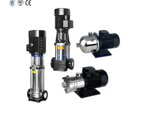
Pump Selection Criteria
The high-pressure pump is a critical RO system component that directly affects energy consumption and operating cost. Selection factors include: (1) Operating pressure – determined by feed water osmotic pressure plus membrane net driving pressure; (2) Flow rate – feed flow required for the design permeate flow at target recovery; (3) Pump type – multistage centrifugal pumps (most common for BWRO, 70-85% efficiency), positive displacement plunger pumps (high efficiency 85-92% for SWRO), or split-case centrifugal pumps (large systems); (4) Material compatibility – 316 SS wetted parts for brackish water, super duplex SS for seawater; (5) Variable frequency drive (VFD) – recommended for flow control and energy optimization, typically reducing energy consumption by 10-20% compared to fixed-speed operation with throttle valves.
7. What Are the Key Operational Parameters for RO Systems?
Normalized Performance Monitoring
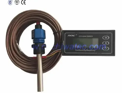
RO system performance must be monitored using normalized parameters that account for temperature, pressure, and feed water quality variations. Key parameters include: (1) Normalized permeate flow – a 10-15% decline from baseline signals membrane fouling; (2) Normalized salt rejection – a decrease of 0.5-1.0% from baseline indicates membrane damage or seal leakage; (3) Normalized pressure drop – a 15-20% increase across stages indicates fouling or scaling; (4) Temperature-corrected flux – standard reference temperature is 25 degrees C.
Operating Limits
- Maximum element recovery per vessel: 18-20% for BWRO; 12-15% for SWRO.
- Maximum feed flow per 8-inch element: 17 m³/h for BWRO; 12 m³/h for SWRO.
- Minimum concentrate flow per 8-inch element: 2.5-3.5 m³/h to prevent scaling and concentration polarization.
- Maximum feed pressure: 41 bar for standard BWRO elements; 83 bar for SWRO elements.
- Feed water temperature: 5-45 degrees C for standard TFC membranes.
- Feed water pH: 2-11 during operation, 1-13 during cleaning.
8. How to Control Membrane Fouling in RO Systems?
Types of Membrane Fouling
- Scaling: Precipitation of sparingly soluble salts (CaCO&sub3;, CaSO&sub4;, BaSO&sub4;, SrSO&sub4;, SiO&sub2;) on the membrane surface. Controlled by antiscalant dosing, limiting recovery, and maintaining feed water pH below saturation levels.
- Biofouling: Microbial growth on membrane surfaces, particularly in warm feed water with nutrients. Controlled by chlorine dosing (with dechlorination before membranes), continuous or periodic biocide treatment, and maintaining cross-flow velocity above 0.1 m/s.
- Colloidal fouling: Deposition of fine particles, clay, silt, or metal oxides. Prevented by effective pretreatment achieving SDI below 3.
- Organic fouling: Adsorption of natural organic matter (NOM) or oil on membrane surfaces. Controlled by coagulation pretreatment, activated carbon, or UF pretreatment.
9. What Is the Recommended Maintenance Schedule for RO Equipment?
Routine Maintenance
- Daily: Record feed pressure, interstage pressure, concentrate pressure, permeate flow, concentrate flow, feed conductivity, permeate conductivity, feed temperature, and pH. Calculate and log normalized parameters.
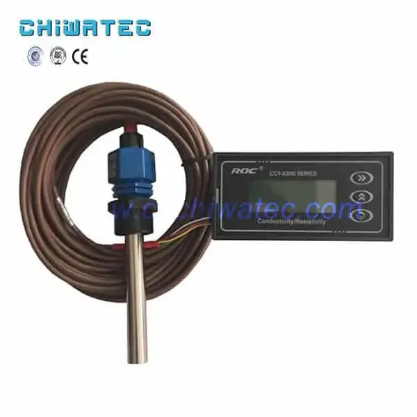
- Weekly: Check and calibrate online conductivity meters and pH probes. Inspect feed and product water quality trends. Verify chemical dosing pump operation and chemical tank levels.
- Monthly: Replace cartridge filter elements. Inspect high-pressure pump seals and couplings. Test all automatic valves for proper operation. Collect feed water sample for SDI measurement.
- Quarterly: Conduct detailed performance analysis and compare normalized data against baseline. Plan CIP cleaning if normalized flow has declined by 10-15% or pressure drop has increased by 15-20%.
- Annually: Complete membrane element analysis (salt rejection, flow rate, pressure drop) for representative elements. Inspect pressure vessel O-rings and interconnectors. Replace feed water analysis and update design calculations.
10. How to Commission and Start Up a New RO Water Treatment System?
Commissioning Procedure
Proper commissioning is essential for long-term RO system performance: (1) Pretreatment verification – confirm all pretreatment equipment operates correctly, feed water meets SDI below 3 and chlorine below 0.1 ppm; (2) Low-pressure flush – flush membrane elements with permeate or RO-quality water at low pressure (3-4 bar) for 30-60 minutes to remove preservative and trapped air; (3) Gradual pressure ramp-up – increase feed pressure gradually over 30-60 minutes to design operating pressure while monitoring permeate flow and conductivity; (4) Stabilization period – operate at design conditions for 24-72 hours, collecting baseline performance data. Initial permeate should be diverted to drain until conductivity stabilizes below design target; (5) Performance acceptance test – conduct a 24-hour performance test verifying permeate flow, salt rejection, and recovery meet design specifications. Document baseline normalized performance data for future reference.
CHIWATEC provides complete RO water treatment system design, equipment supply, and commissioning services. CHIWATEC engineers deliver custom-engineered RO solutions for industrial, municipal, and commercial applications, ensuring reliable operation and optimal performance.
Conclusion
A comprehensive RO water treatment equipment program encompasses everything from feed water analysis and pretreatment design to membrane array configuration, operational monitoring, and maintenance planning. Each component and parameter must be carefully specified to achieve the required product water quality, recovery rate, and operational reliability. As RO technology continues to advance with lower-energy membranes, smarter monitoring systems, and improved pretreatment methods, the fundamental principles of sound system design remain essential for successful implementation. Contact CHIWATEC today at [email protected] or [email protected] (WhatsApp available) for expert guidance on designing, selecting, and commissioning the ideal RO water treatment system for your application.
Frequently Asked Questions
Q1: What is the typical lifespan of an RO water treatment system?
A well-designed and properly maintained RO system has a service life of 15-20 years. Major components such as pressure vessels, pumps, and piping last this full duration. RO membrane elements require replacement every 2-5 years depending on feed water quality and operating conditions. Pretreatment components (media, carbon, cartridge filters) are periodically replaced according to their individual service schedules.
Q2: How much water does an RO system waste?
Standard brackish water RO systems recover 75-85% of feed water as product water, meaning 15-25% is discharged as concentrate. Seawater RO systems recover 40-50%. Modern high-efficiency systems with two-stage or three-stage arrays can achieve 85-90% recovery for brackish water. Concentrate disposal options include sewer discharge, evaporation ponds, deep well injection, or zero liquid discharge (ZLD) systems for environmentally sensitive areas.
Q3: Can RO systems remove all contaminants from water?
RO membranes remove 95-99% of most dissolved contaminants, including salts, heavy metals, bacteria, viruses, and organic compounds. However, some low-molecular-weight compounds (certain pesticides, solvents, and dissolved gases) may pass through RO membranes. Additional treatment steps such as activated carbon filtration, UV oxidation, or advanced oxidation processes (AOP) may be required for complete contaminant removal in specialized applications.
Q4: What causes low permeate flow from an RO system?
Common causes include: (1) membrane fouling or scaling (check normalized flow trend and pressure drop); (2) low feed water temperature (flow rate decreases by 1.5-2% per degree C below 25 degrees C); (3) low feed pressure (check high-pressure pump performance); (4) clogged cartridge filters (check pressure differential); (5) O-ring leakage or valve misalignment; or (6) membrane degradation or compaction in older systems.
Q5: How do I know when to clean RO membranes?
Clean RO membranes when: normalized permeate flow has declined by 10-15% from baseline; normalized salt rejection has decreased by 0.5-1.0%; normalized pressure drop has increased by 15-20%; or any of these parameters change abruptly. CIP cleaning takes 4-8 hours using alkaline and/or acid cleaning solutions. Most systems require cleaning every 3-6 months, though frequency varies significantly with feed water quality.
Related Resources and Further Reading
- Mineral Water Equipment Process — System design for mineral water RO applications
- Advanced Water Purification System: Process Principles and Flow Diagram — Comprehensive purification system design principles
- Drinking Water Treatment Process Flow: Comprehensive Guide — Drinking water RO system process overview
- Main Process Flow Description of Reverse Osmosis Pure Water Equipment — Detailed RO pure water equipment process flow
- RO Water Treatment Systems by CHIWATEC — Explore CHIWATEC RO system solutions
Do you have a water treatment project we can help with
* Designing,machining,installing,commissioning, customize and one-stop service