Chemical Plant Ultrapure Water System: Complete Design Scheme for RO and Deionization Equipment 2026
Designing an ultrapure water system for a chemical plant? Chemical manufacturing requires ultrapure water with conductivity below 0.1 uS/cm and resistivity above 10 MOhm.cm to prevent contamination in chemical reactions, equipment corrosion, and product quality issues. A well-designed system combines multi-stage pretreatment, reverse osmosis (RO), and deionization (DI) polishing – achieving 99% contaminant removal through eight integrated treatment stages. CHIWATEC specializes in custom-engineered ultrapure water systems for chemical plants, delivering turnkey solutions from design through commissioning.
System Design Overview: Key Parameters and Standards
A chemical plant ultrapure water system must be designed around specific feed water parameters and target effluent quality. Typical inlet requirements include: city tap water or groundwater (water samples must be tested), inlet pressure above 0.3 MPa, and inlet conductivity below 800 uS/cm.
- Target effluent quality: Conductivity below 0.1 uS/cm, resistivity above 10 MOhm.cm, silica below 20 ppb, TOC below 50 ppb, and particle count below 100 particles/mL at 0.2 microns.
- Feed water variability: Chemical plants often experience seasonal fluctuations in feed water quality. Design must include a 20-30% safety margin in pretreatment capacity to handle peak turbidity and TDS loads.
- Flow rate design: System capacity is calculated based on peak chemical production demand plus regeneration downtime. Typical chemical plant systems range from 5-100 m3/h with storage tanks sized for 2-4 hours of peak demand.
- Applicable standards: Systems must comply with GB/T 6682-2008 (China laboratory water), ASTM D1193-91 Type I, or customer-specific chemical process water specifications.
Stage 1-2: Multi-Media and Activated Carbon Pretreatment
The first two pretreatment stages remove suspended solids, chlorine, and organic compounds that would foul downstream RO membranes and DI resins. Stage 1 uses a quartz sand multi-media filter to remove sediment, rust, colloidal matter, and suspended particles above 20 microns. Stage 2 uses a nut shell activated carbon filter to remove color, odor, biochemical organic matter, residual chlorine, and chlorine-based disinfectants.
- Multi-media filter design: Graded layers of quartz sand (0.5-1.2 mm) with a bed depth of 1,000-1,500 mm. Filtration rate of 8-15 m/h with automatic backwash triggered by pressure differential or timer.
- Activated carbon specifications: Iodine number above 900, hardness above 95%, effective size of 0.6-0.9 mm. Empty bed contact time (EBCT) of 10-20 minutes for effective chlorine and organic removal.
- Backwash requirements: Both filters require backwash at 30-50 m/h for 10-15 minutes. Backwash water consumption is 2-5% of treated water volume – important for chemical plant water balance calculations.
Stage 3-4: Water Softening and Precision Filtration
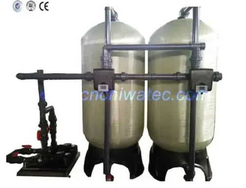
Stage 3 uses cation resin to soften the water by removing calcium and magnesium hardness that would otherwise scale the RO membranes. Stage 4 employs a 5-micron cartridge precision filter to capture any remaining particulates before the RO membranes.
- Softener design: Strong acid cation (SAC) resin in sodium form, with a hardness removal capacity of 1.8-2.0 eq/L. Target effluent hardness below 0.5 ppm as CaCO3. Regeneration with 8-12% NaCl solution, consuming 150-240 g of salt per liter of resin.
- Precision filter specifications: 5-micron absolute rating polypropylene or wound cartridges, typically 20-40 inch length in a 7-30 cartridge housing. Replacement when pressure differential reaches 1 bar, typically every 1-3 months.
- Protection role: These stages are critical for RO membrane protection. Hardness breakthrough above 1 ppm will cause calcium carbonate scaling on RO membranes, reducing salt rejection and requiring chemical cleaning.
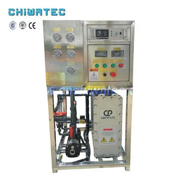
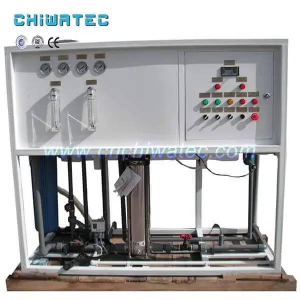
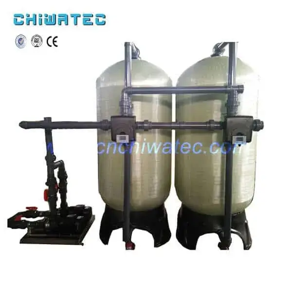
Stage 5: Reverse Osmosis Host for Deep Desalination
The RO host is the core desalination stage, using imported thin-film composite polyamide RO membrane elements to remove 97-99% of dissolved salts. The RO system operates at 10-15 bar for brackish feed water, producing permeate with conductivity of 10-30 uS/cm.
- Membrane configuration: Standard 8-inch spiral-wound elements in a tapered array (e.g., 2:1 or 4:2:1 pressure vessel ratio) to maintain optimal cross-flow velocity across stages. Typical flux rate: 15-25 LMH for chemical plant applications.
- Recovery rate: 75-85% for single-stage systems. Two-stage arrays achieve 85-90% recovery, reducing feed water consumption and wastewater generation.
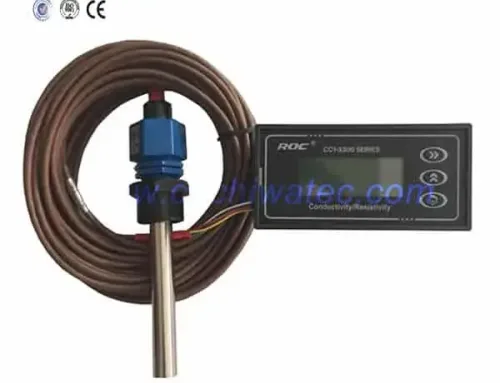
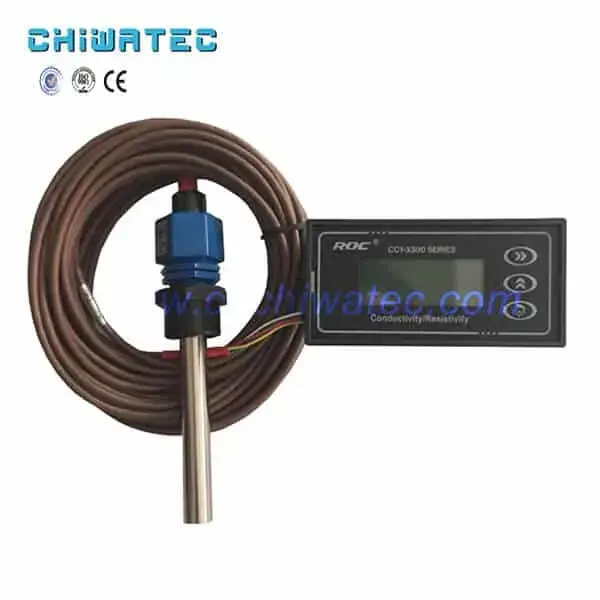
- Monitoring and control: Continuous monitoring of feed pressure, interstage pressure, permeate flow, concentrate flow, and permeate conductivity. Automatic shut-off on high conductivity or low flow to protect downstream equipment.
- CIP system: Integrated clean-in-place system with alkaline (pH 11-12) and acid (pH 2-3) cleaning solutions. Typical cleaning frequency every 3-6 months.
A comprehensive design process for RO desalination in ultrapure water systems provides detailed membrane array configurations and design calculations for chemical plant applications.
Stage 6: Deionization Polishing for 18.2 MOhm.cm Water
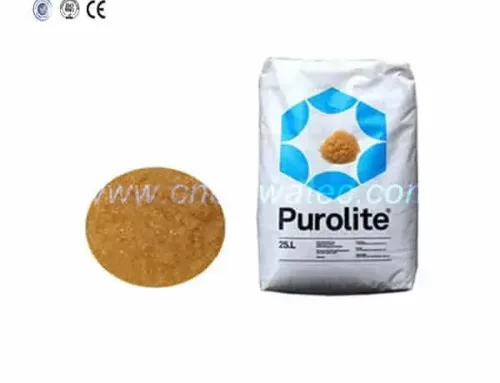
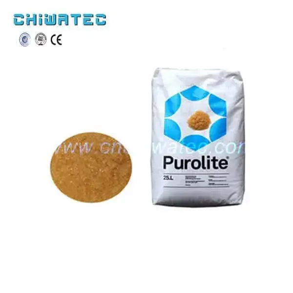
Deionization is the final polishing stage that boosts water quality from RO-grade (10-30 uS/cm) to ultrapure-grade (below 0.1 uS/cm). Water from the RO host enters a pure water tank, then is pumped through a mixed-bed DI vessel containing intimately mixed cation and anion exchange resins.
- Mixed-bed DI design: Cation-to-anion resin ratio of 40:60 or 50:50 depending on feed water chemistry. Vessel with internal distribution system for water collection, regenerant distribution, and compressed air mixing.
- Performance: Achieves effluent conductivity of 0.055-0.1 uS/cm (10-18.2 MOhm.cm) through the multi-bed effect of thousands of sequential cation-anion exchange stages within a single vessel.
- Regeneration: Resin separation by hydraulic backwashing, followed by acid (4-8% HCl) regeneration of the cation layer and caustic (4-6% NaOH) regeneration of the anion layer. Complete cycle takes 2-4 hours.
- EDI alternative: For chemical plants requiring continuous operation without regeneration downtime, electrodeionization (EDI) can replace mixed-bed DI. EDI operates without chemical regeneration, reducing operating costs by 30-50% over 5 years.
Stage 7-8: Microfiltration and Sterilization for Final Protection
The final two stages ensure that ultrapure water quality is maintained through to the point of use. Stage 7 is a microfiltration device that captures any resin particles that may escape from the DI vessel. Stage 8 is a sterilization system using an ozone generator or ultraviolet sterilizer to prevent bacterial growth in the storage and distribution system.
- Microfiltration: 0.45 or 0.22 micron absolute filters installed after the DI vessel to capture resin fines, broken bead fragments, and any microbial debris. Essential for protecting downstream chemical process equipment from particulate contamination.
- UV sterilization: 254 nm UV-C light at a dose of 30-40 mJ/cm2 provides 99.99% inactivation of bacteria and viruses without chemical additives. UV is preferred when ozone residual must be avoided.
- Ozone sterilization: Ozone generator producing 0.1-0.4 ppm residual ozone in the storage tank. Ozone provides continuous disinfection throughout the distribution loop and decomposes to oxygen with no chemical residual.
- Sterilization rate: Both methods achieve 99.9% sterilization efficiency when properly designed. The choice between UV and ozone depends on whether residual disinfection in the distribution loop is required.
Selecting the Right Ultrapure Water System for Your Chemical Plant
The optimal system configuration depends on your feed water quality, target purity, flow rate, and operational preferences. Here is a practical selection framework:
- For standard chemical processes: RO + mixed-bed DI is the most cost-effective configuration, achieving 10-18.2 MOhm.cm at USD 0.50-1.00/m3 total operating cost.
- For continuous operation with no regeneration downtime: RO + EDI eliminates chemical regeneration cycles and reduces operating costs by 30-50%, though capital cost is 20-40% higher.
- For high-purity chemical synthesis: RO + EDI + mixed-bed polishing provides the highest water quality (18.2 MOhm.cm consistently) with redundant treatment for critical processes.
- For challenging feed water (high TDS or variable quality): Two-stage RO + EDI or two-stage RO + mixed-bed DI with enhanced pretreatment and larger safety margins.
An introduction to industrial ultrapure water equipment provides additional guidance on system sizing and equipment selection for chemical plant applications.
Frequently Asked Questions
Q1: What is the typical cost of an ultrapure water system for a chemical plant?
Capital cost varies significantly with capacity and configuration. A 10 m3/h RO + mixed-bed DI system typically costs USD 100,000-250,000. A 50 m3/h system with RO + EDI ranges from USD 400,000-800,000. Operating costs are USD 0.50-1.00/m3 for RO + DI and USD 0.20-0.40/m3 for RO + EDI.
Q2: How often does a chemical plant ultrapure water system need maintenance?
Daily monitoring of conductivity, flow rates, and pressure drops is essential. Cartridge filters need replacement every 1-3 months. RO membranes require chemical cleaning every 3-6 months and replacement every 2-5 years. DI resin requires regeneration every 1-4 weeks and replacement every 3-5 years.
Q3: Can the same system handle both ultrapure and general process water?
Yes, with a split-stream design. A common approach is to size the RO system for total plant water demand, then split the RO permeate: one stream goes to general process water users, and the other passes through DI or EDI polishing for ultrapure applications. This maximizes RO utilization while minimizing polishing costs.
Q4: What causes conductivity spikes in ultrapure water systems?
Common causes include: DI resin exhaustion (most common), RO membrane degradation (increased salt passage), air ingress into the distribution system (CO2 absorption forms carbonic acid), and bacterial regrowth in the storage tank. Online conductivity monitoring with automatic divert-to-drain on high conductivity is essential for protecting chemical processes.
Q5: Is EDI always better than mixed-bed DI for chemical plants?
Not always. EDI has higher capital cost (20-40% premium) but lower operating cost (30-50% savings). EDI is better for systems above 5 m3/h requiring continuous operation. Mixed-bed DI is more economical for smaller systems, intermittent operation, or when existing chemical handling infrastructure is already in place for other plant processes.
Conclusion and CTA
A well-designed chemical plant ultrapure water system integrates eight treatment stages – from multimedia filtration through RO desalination and DI polishing to final sterilization – each stage protecting the next while progressively improving water quality to the required 0.1 uS/cm or better. The choice between mixed-bed DI and EDI, UV and ozone sterilization, and single or two-stage RO depends on your specific feed water, flow requirements, and operational preferences. Contact CHIWATEC today at [email protected] or [email protected] (WhatsApp available) for expert guidance on designing, engineering, and commissioning the ideal ultrapure water system for your chemical plant.
Related Resources and Further Reading
- Ultrapure Water for Electronics Industry: Equipment Features, Process Flow, and Applications – Cross-industry ultrapure water system reference
- Comprehensive Design Process for Reverse Osmosis Desalination in Ultrapure Water Systems – Detailed RO design methodology
- Comprehensive Guide to Ultrapure Water Equipment Process Flow – Process flow design and optimization
- Introduction of Industrial Ultrapure Water Equipment – Industrial system overview and selection guide
- EDI Ultrapure Water Equipment by CHIWATEC – Explore EDI solutions for chemical plant applications
Do you have a water treatment project we can help with
* Designing,machining,installing,commissioning, customize and one-stop service