How Reverse Osmosis Membranes Work: Complete Guide to RO Membrane Working Principle and Separation Process 2026
The RO membrane working principle is based on a deceptively simple concept: when pressure greater than the natural osmotic pressure is applied to a concentrated solution, water molecules are forced through a semi-permeable membrane while dissolved solids are rejected. Understanding this RO membrane working principle is essential for anyone involved in water treatment system design, operation, or maintenance.
Fundamental RO Membrane Working Principle
A reverse osmosis membrane is a semi-permeable barrier that allows solvent molecules (water) to pass through while rejecting dissolved solutes (salts, minerals, organic compounds). The RO membrane working principle relies on three key factors:
| Factor | Description | Typical Value |
| Applied pressure | Pressure exceeding the feed water osmotic pressure, forcing water through the membrane against the natural osmotic gradient | 100-450 psi (7-31 bar) for brackish water RO; 800-1,200 psi (55-83 bar) for seawater RO |
| Semi-permeable membrane | A thin-film composite (TFC) polyamide layer that selectively passes water while rejecting 95-99.5% of dissolved salts | Pore size < 0.001 μm (1 nm) — effectively non-porous for dissolved ions |
| Concentration gradient | The difference in solute concentration across the membrane drives the osmotic pressure that must be overcome | Osmotic pressure: ~11 psi per 1,000 mg/L TDS |
During operation, feed water flows across the membrane surface under pressure. The applied pressure must exceed the feed water’s osmotic pressure — approximately 11 psi (0.75 bar) per 1,000 mg/L of dissolved solids. For typical brackish water at 2,000 mg/L TDS, the minimum applied pressure is about 22 psi (1.5 bar), though practical operating pressures are 100-225 psi (7-15 bar) to achieve adequate flux and recovery.
Understanding Osmosis and Reverse Osmosis
To understand how reverse osmosis membranes work, it is necessary to first understand the natural phenomenon of osmosis:
Natural Osmosis
When a semi-permeable membrane separates two solutions of different concentrations, water naturally migrates from the low-concentration side (low TDS) to the high-concentration side (high TDS) through the membrane. This flow continues until the pressure difference across the membrane equals the osmotic pressure of the concentrated solution. This is a spontaneous, entropy-driven process.
Reverse Osmosis
Reverse osmosis reverses this natural flow by applying external pressure to the concentrated solution side that exceeds the osmotic pressure. When this happens, water molecules are forced to flow from the high-concentration side to the low-concentration side — the opposite direction of natural osmosis. This produces purified water (permeate) on the low-pressure side while the remaining feed water becomes increasingly concentrated (concentrate or reject) on the high-pressure side.
| Parameter | Osmosis | Reverse Osmosis |
| Driving force | Concentration gradient (spontaneous) | Applied hydraulic pressure |
| Water flow direction | Low TDS → High TDS | High TDS → Low TDS |
| Energy requirement | None (natural process) | High-pressure pump (0.5-4 kWh/m³) |
| Result | Equalizes concentration | Separates pure water from dissolved solids |
Structure of a Thin-Film Composite (TFC) RO Membrane
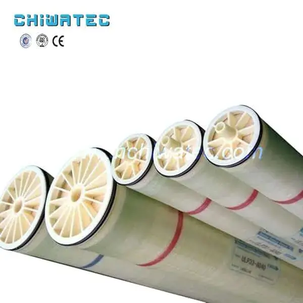
Modern RO membranes are thin-film composite (TFC) polyamide membranes, typically configured as spiral-wound elements. The membrane consists of three layers:
- Polyamide active layer (0.1-0.2 μm) — The ultra-thin, cross-linked polyamide barrier that performs the actual salt rejection. This layer is created through an interfacial polymerization reaction on the surface of the support layer. The polyamide chemistry determines the membrane’s rejection characteristics, permeability, and chlorine tolerance.
- Polysulfone support layer (~40 μm) — A porous polysulfone layer that provides mechanical support for the fragile polyamide active layer while offering minimal hydraulic resistance to permeate flow.
- Polyester backing fabric (~120 μm) — A non-woven polyester fabric that provides structural strength for the membrane element and facilitates permeate water collection and transport to the permeate tube.
The membrane is folded and wound around a central permeate collection tube in a spiral configuration, with feed spacers separating the membrane leaves to create flow channels. A standard 4-inch diameter element contains approximately 7-8 m² of membrane area, while an 8-inch element contains 30-40 m².
Mass Transport Mechanisms in RO Membrane Separation
Two primary models describe water and solute transport through RO membranes:
Solution-Diffusion Model
The widely accepted solution-diffusion model describes water transport as a three-step process: 1) water molecules adsorb into the membrane polymer at the feed side, 2) water diffuses through the dense polyamide layer under a chemical potential gradient, and 3) water desorbs from the membrane at the permeate side. Solute transport follows a similar mechanism but at a much slower rate due to the larger molecular size relative to the polymer free volume.
Pore Flow Model
An alternative model suggests that RO membranes contain micro-pores (approximately 0.5-1.0 nm diameter) through which water flows under hydraulic pressure, while solutes are rejected based on their size relative to the pore diameter. In practice, the true transport mechanism combines elements of both models, with the dense polyamide layer exhibiting both diffusive and convective transport characteristics.
| Parameter | Solution-Diffusion Model | Pore Flow Model |
| Water flux (Jₜ) | A(ΔP – Δπ) | K(ΔP – Δπ) |
| Solute flux (Jₛ) | B(Cf – Cp) | Jw · Cp |
| Salt rejection | R = 1 – Cp/Cf | R = 1 – Cp/Cf |
Where A = membrane water permeability coefficient, B = solute permeability coefficient, ΔP = transmembrane pressure, Δπ = osmotic pressure difference, Cf = feed concentration, Cp = permeate concentration.
Key Factors Affecting RO Membrane Performance
- Feed pressure — Higher pressure increases water flux proportionally (flux ∝ ΔP – Δπ) but also increases the specific energy consumption. Optimal pressure balances productivity against energy cost.
- Feed temperature — Membrane flux increases by approximately 2-3% per °C as water viscosity decreases and diffusion rates increase. Standard RO design is typically based on 25°C, with temperature correction factors applied for other operating temperatures.
- Feed TDS and osmotic pressure — Higher TDS increases osmotic pressure, reducing net driving pressure (ΔP – Δπ) and thus decreasing flux. Seawater RO systems require much higher pressures (800-1,200 psi) than brackish water systems.
- Recovery rate — Higher recovery rates (permeate flow / feed flow) increase the average feed-side concentration, raising osmotic pressure and increasing the risk of scaling. Typical single-element recovery is 8-15%, while a 7-element pressure vessel operates at 50-75% overall recovery.
- Membrane fouling — Fouling from suspended solids, organic matter, biological growth, or scaling reduces effective membrane area and increases pressure drop. Proper pretreatment and regular cleaning are essential for maintaining performance.
Frequently Asked Questions About RO Membrane Working Principle
Q1: What pressure is needed for reverse osmosis?
The required pressure depends on feed water salinity. Brackish water (1,000-5,000 mg/L TDS) typically requires 100-225 psi. Seawater (30,000-45,000 mg/L TDS) requires 800-1,200 psi. The applied pressure must always exceed the feed water’s osmotic pressure by a sufficient margin (typically 50-100 psi) to achieve practical water flux.
Q2: Can RO membranes remove all contaminants from water?
RO membranes reject 95-99.5% of dissolved inorganic salts and 99%+ of bacteria, viruses, and particles > 0.001 μm. However, some small, uncharged molecules (such as dissolved gases like CO₂ and certain low-molecular-weight organic compounds) can pass through the membrane. For critical applications, RO is combined with additional treatment steps such as ion exchange, UV oxidation, or activated carbon filtration.
Q3: Why is pre-treatment necessary before RO membranes?
Pretreatment is essential to protect RO membranes from fouling, scaling, and chemical damage. Typical pretreatment includes multimedia filtration for suspended solids removal, activated carbon for chlorine removal, water softening or antiscalant dosing for scale prevention, and cartridge filtration as a safety barrier.
Q4: What is the lifespan of an RO membrane?
Under proper operating conditions with adequate pretreatment and regular cleaning, RO membranes typically last 2-5 years. Factors that reduce membrane life include inadequate pretreatment, high fouling rates, frequent chemical cleaning, chlorine exposure (for TFC membranes), and operating outside the manufacturer’s specified pH and temperature ranges.
Q5: What is the difference between RO and ultrafiltration (UF)?
RO membranes have pore sizes below 0.001 μm and reject dissolved ions via the solution-diffusion mechanism. UF membranes have pore sizes of 0.01-0.05 μm and reject particles, colloids, and microorganisms by size exclusion. UF membranes operate at much lower pressures (10-50 psi) but cannot remove dissolved salts. RO and UF are often used together in treatment trains, with UF serving as pretreatment for RO.
Conclusion and Call to Action
The RO membrane working principle — applying pressure greater than osmotic pressure to drive water through a semi-permeable membrane — is the foundation of modern desalination and water purification technology. From the thin-film composite membrane structure to the solution-diffusion transport mechanism, understanding how RO membranes work is essential for selecting the right system, optimizing performance, and troubleshooting operational issues.
CHIWATEC supplies a complete range of RO membranes and reverse osmosis systems, including Vontron, Dupont FilmTec, and Hydranautics elements. Contact us at [email protected] or [email protected] for expert advice on RO membrane selection, system design, and operation.
Related Resources and Further Reading
- RO Membrane Performance Parameters: Technical Standards for Salt Rejection and Flux
- Difference Between RO Membrane and Ultrafiltration Membrane: Characteristics and Applications Compared
- Reverse Osmosis Membrane Characteristics: 6 Essential Properties for Optimal Performance
- Introduction of RO Reverse Osmosis Membrane and the Advantages of Reverse Osmosis Membrane Technology
- RO Membrane Products
Do you have a water treatment project we can help with
* Designing,machining,installing,commissioning, customize and one-stop service
 English
  Spanish
  Portuguese