Electroplating Wastewater Treatment Process Flow: Complete Project Guide 2026
Electroplating is one of the three most polluting industries globally, generating approximately 4 billion m³ of wastewater annually in China alone. An effective electroplating wastewater treatment process flow is critical for removing toxic heavy metals (Cr, Ni, Cu, Zn), cyanides, acid-alkali compounds, and organic brighteners before discharge. This guide walks through the complete project process — from wastewater source classification and pretreatment to chemical treatment, membrane separation, biological polishing, and compliant reuse — helping engineers and plant managers design a reliable treatment system that meets discharge standards while enabling water recycling.
Sources and Classification of Electroplating Wastewater
Understanding wastewater sources is the foundation of any electroplating wastewater treatment process flow. Electroplating wastewater originates from three main streams:
| Wastewater Type | Source | Key Pollutants | Concentration Range |
| Cyanide wastewater | Plating bath rinsing, cyanide-based plating solutions | CN⁻, Cu(CN)₃²⁻, Zn(CN)₄²⁻ | 20–70 mg/L as CN⁻ |
| Chromium wastewater | Chromium plating, chromate passivation rinses | Cr⁶⁺, Cr³⁺, heavy metals | 20–100 mg/L as Cr |
| Heavy metal wastewater | Nickel, copper, zinc plating rinses | Ni²⁺, Cu²⁺, Zn²⁺, Fe²⁺ | 10–200 mg/L depending on process |
| Acid-alkali wastewater | Pre-treatment cleaning, stripping, surface activation | HCl, H₂SO₄, NaOH, degreasing agents | pH 2–12 |
| Comprehensive wastewater | Mixed streams from all workshop sections | Combination of above + organic brighteners | Variable |
Each stream requires a specific treatment stage in the overall electroplating wastewater treatment process flow. Separate collection at source is essential — mixing incompatible streams (e.g., cyanide and acidic wastewater) can generate toxic hydrogen cyanide gas.
Project Design Principles and Pretreatment Stage
A successful electroplating wastewater treatment project follows three key design principles:
- Source separation — Independent collection pipes for cyanide, chromium, heavy metal, and acid-alkali wastewater streams
- Flow equalization — Balancing tanks to buffer flow rate fluctuations from batch plating operations
- Pretreatment — Removal of oil, grease, suspended solids, and large particles before entering the main treatment train
The pretreatment stage typically includes an oil-water separator, screening (1–2 mm mesh), and a pH adjustment tank where incoming wastewater is neutralized to pH 7–9 using lime or caustic soda. This step protects downstream equipment — pumps, membrane modules, and chemical dosing systems — from fouling and damage.
Cyanide Oxidation and Chromium Reduction in the Electroplating Wastewater Treatment Process Flow
Alkaline Chlorination for Cyanide Removal
Cyanide is oxidized in two stages using sodium hypochlorite (NaClO) under alkaline conditions (pH 10–11):
- Stage 1: CN⁻ → CNO⁻ (cyanate), pH 10.5–11, ORP +350 mV, reaction time 10–30 min
- Stage 2: CNO⁻ → CO₂ + N₂, pH 8–8.5, ORP +650 mV, extended reaction time
This two-stage alkaline chlorination achieves >99.9% cyanide removal and produces harmless nitrogen gas. For high-concentration cyanide wastewater (>200 mg/L), electrolytic oxidation is preferred as a pre-treatment step to reduce chemical consumption.
Ferrite Method for Chromium-Containing Wastewater
Hexavalent chromium (Cr⁶⁺) is reduced to trivalent chromium (Cr³⁺) using ferrous sulfate (FeSO₄) at pH 2–3:
- Cr⁶⁺ + 3Fe²⁺ → Cr³⁺ + 3Fe³⁺ (reduction step)
- Addition of alkali (NaOH) precipitates Cr(OH)₃ and Fe(OH)₃ simultaneously
- Air oxidation and heating (60–70°C) convert the mixed hydroxide into stable ferrite (MFe₂O₄), which is non-leachable and safe for landfill
The ferrite method is widely used in the electroplating wastewater treatment process flow because it achieves simultaneous removal of Cr³⁺ and other heavy metal ions in a single precipitation step.
Heavy Metal Removal by Chemical Precipitation
After cyanide and chromium treatment, the combined wastewater enters the chemical precipitation stage where heavy metals are removed as insoluble hydroxide or sulfide precipitates:
| Metal Ion | Precipitant | Optimum pH | Removal Efficiency |
| Ni²⁺ | NaOH, Ca(OH)₂ | 9.5–10.5 | >99% |
| Cu²⁺ | NaOH, Na₂S | 8.5–9.5 | >99% |
| Zn²⁺ | NaOH | 9.0–10.0 | >98% |
| Cr³⁺ | NaOH | 8.0–9.0 | >99% |
Flocculants (PAM at 1–5 mg/L, PAC at 20–50 mg/L) are added after precipitation to enhance sludge settling in the clarifier. The resulting sludge is dewatered using a filter press or centrifuge to ~20–30% solids content before disposal.
Membrane Separation in Electroplating Wastewater Treatment Process Flow
Membrane technology has become an integral part of modern electroplating wastewater treatment process flow due to its ability to recover valuable metals and produce high-quality reuse water:
- Ultrafiltration (UF) — Removes suspended solids and colloidal particles (0.01–0.1 µm), protecting downstream RO membranes. Typical flux: 60–100 L/m²·h at 1–2 bar
- Nanofiltration (NF) — Selectively separates divalent heavy metal ions (Ni²⁺, Cu²⁺) from monovalent ions. Metal rejection: 90–98%. Operating pressure: 5–15 bar
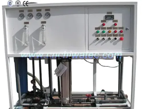
- Reverse Osmosis (RO) — Removes >99% of all dissolved metal ions. Produces permeate suitable for reuse as plating rinse water. Operating pressure: 10–30 bar
- Membrane Bioreactor (MBR) — Combines activated sludge with membrane filtration for organic removal and solid-liquid separation in the biological treatment stage
The investment recovery period for membrane integration in electroplating wastewater treatment is typically 1.5–3 years, primarily through water reuse (reducing fresh water consumption by 60–80%) and metal recovery.
Biological Polishing for Organic Removal
After chemical and membrane treatment, remaining organic pollutants — chelating agents, surfactants, and organic brighteners — require biological polishing:
- Activated sludge process — Aerobic treatment with MLSS of 3000–5000 mg/L, HRT 8–24 hours, achieving 70–85% COD removal
- Biological Aerated Filter (BAF) — Fixed-film biological reactor with 5–10 mm media, achieving 80–90% COD removal at higher loading rates
- Moving Bed Biofilm Reactor (MBBR) — Suspended biofilm carriers, suitable for high-salinity electroplating wastewater, 75–85% COD reduction
Biological treatment is typically placed at the end of the electroplating wastewater treatment process flow to handle residual organic load before final discharge or advanced treatment.
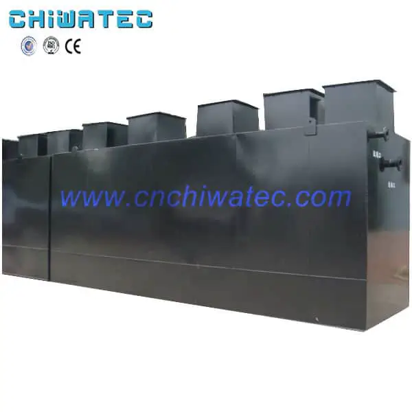
Complete Process Flow Diagram for Electroplating Wastewater Projects
A complete electroplating wastewater treatment project typically follows this sequence:
- Source segregation — Cyanide, chromium, heavy metal, acid-alkali streams collected separately
- Equalization tank — 8–12-hour holding capacity to smooth flow variations
- Pre-treatment — Oil removal, pH adjustment, screening
- Cyanide oxidation — Two-stage alkaline chlorination (pH 10.5→8.5)
- Chromium reduction — Ferrite method (FeSO₄ + alkali + heating)
- Chemical precipitation — pH 9–10.5 with PAM flocculation + clarification
- Membrane separation — UF → NF/RO for metal recovery and water reuse
- Biological polishing — Activated sludge / BAF / MBBR for organic removal
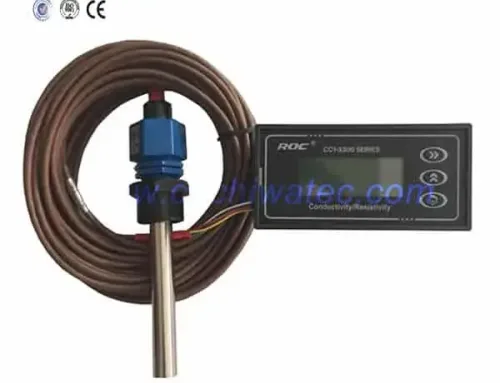
- Final monitoring — Continuous pH, COD, heavy metal analyzers + discharge to standard
Frequently Asked Questions
What is the standard process flow for electroplating wastewater treatment?
The standard electroplating wastewater treatment process flow includes source segregation, cyanide oxidation, chromium reduction, chemical precipitation, membrane separation (UF/NF/RO), biological polishing, and final discharge or reuse. Each step is designed to target specific pollutant categories.
How do you treat cyanide in electroplating wastewater?
Cyanide is treated by two-stage alkaline chlorination using sodium hypochlorite at pH 10.5–11 (stage 1) and pH 8–8.5 (stage 2), completely oxidizing CN⁻ to harmless CO₂ and N₂. For high-concentration streams, electrolytic oxidation serves as a pre-treatment.
Can electroplating wastewater be recycled?
Yes. With membrane technology (RO/NF), 60–80% of treated electroplating wastewater can be recycled back as plating rinse water. The recovered metal concentrates can also be reused in the plating bath, reducing raw material costs and achieving near-zero liquid discharge goals.
What is the cost of an electroplating wastewater treatment project?
Costs vary widely based on capacity, treatment standards, and technology selection. A typical 100–500 m³/day system with chemical + membrane + biological treatment ranges from USD 200,000 to 800,000. The investment recovery period through water reuse and metal recovery is 1.5–3 years.
What discharge standards apply to electroplating wastewater?
In China, GB 21900-2008 specifies limits: total Cr ≤ 0.5 mg/L, Cr⁶⁺ ≤ 0.1 mg/L, total Ni ≤ 0.1 mg/L, total Cu ≤ 0.3 mg/L, total Zn ≤ 1.0 mg/L, CN⁻ ≤ 0.2 mg/L, and COD ≤ 50 mg/L for existing facilities. New facilities face stricter limits under the “Table 3” standards.
Conclusion and Call to Action
Designing an efficient electroplating wastewater treatment process flow requires careful consideration of wastewater characteristics, discharge standards, and water reuse targets. From source segregation through chemical treatment, membrane separation, and biological polishing, each stage plays a critical role in achieving compliant, cost-effective treatment. CHIWATEC specializes in custom-designed electroplating wastewater treatment systems, offering engineering, manufacturing, installation, and commissioning services for projects from 10 m³/day to 5,000 m³/day. Contact our team today to discuss your project requirements: [email protected] or [email protected].
Related Resources and Further Reading
- Electroplating Wastewater Treatment Technologies: Membrane Separation, Ion Exchange, and Biological Methods (Part 3) 2026
- Electroplating Wastewater Treatment Equipment: Complete System Guide 2026
- Pickling Wastewater Treatment: Complete Guide to Sources, Composition and Treatment Methods 2026
- Biological Aerated Filter (BAF) Technology: Complete Guide to Working Principle, Design, and Applications 2026
- CHIWATEC Wastewater Treatment Systems
Do you have a water treatment project we can help with
* Designing,machining,installing,commissioning, customize and one-stop service
 English
  Spanish
  Portuguese