Ultrapure Water for Electronics Industry: Equipment Features, Process Flow, and Applications Guide (2026 Updated)
Ultrapure water (UPW) is an essential utility in the electronics industry, used extensively in semiconductor fabrication, printed circuit board (PCB) manufacturing, liquid crystal display (LCD) production, and other high-tech microelectronics processes. The electronics industry demands water with resistivity of 18.2 MOhm-cm, TOC below 2 ppb, and particle counts near zero — specifications that require sophisticated multi-stage treatment systems. Xi’an CHIWATEC designs and manufactures complete ultrapure water equipment tailored to the stringent requirements of electronics manufacturing facilities worldwide.
*Last Updated: March 2026
Why This Guide Matters
The global ultrapure water market for the electronics industry was valued at approximately USD 6.5 billion in 2025 and is projected to reach USD 12.8 billion by 2035, expanding at a CAGR of 7.0% (Grand View Research, 2025). A single advanced semiconductor fabrication facility can consume 4-8 million gallons of ultrapure water per day, with water costs representing up to 10% of total operational expenses. As chip geometries shrink to 3 nm and below, the water quality requirements become increasingly stringent — a single particle larger than 0.05 microns can render an entire wafer batch defective. Understanding the equipment features, process flows, and application requirements of ultrapure water systems is critical for electronics manufacturers seeking to maintain production yields and control operational costs.
Key Industry Trends (2026 Update)
- Sub-3 nm node water quality demands: Advanced semiconductor nodes (3 nm and below) require UPW with TOC below 1 ppb, dissolved oxygen below 1 ppb, and resistivity of 18.2 MOhm-cm maintained at the point of use. New double-pass RO and continuous electrodeionization (CEDI) configurations are being deployed to meet these specifications.
- Water recycling and zero-liquid discharge (ZLD): Electronics manufacturers are implementing UPW recycling systems that recover 85-95% of spent rinse water, reducing raw water intake by up to 70%. ZLD systems using brine concentrators and crystallizers are becoming standard in new fab designs.
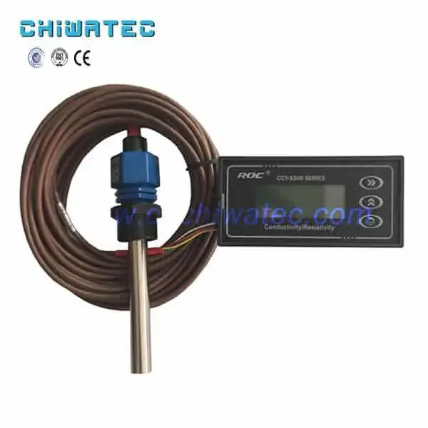
- IoT-enabled real-time water quality monitoring: Online particle counters, TOC analyzers, and resistivity sensors with cloud-based data logging enable real-time water quality tracking and predictive maintenance, reducing unplanned downtime by 35-50% in ultrapure water plants.
- PFAS compliance in electronics water systems: New regulations (EPA PFAS MCLs, 2024-2026) are driving electronics manufacturers to install granular activated carbon (GAC) and ion exchange polishing systems specifically for PFAS removal from UPW feed water and wastewater streams.
1. What Are the Key Features of Ultrapure Water Equipment for the Electronics Industry?
Multi-Stage Pretreatment System
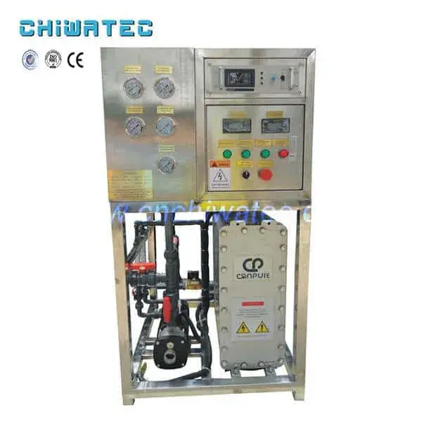
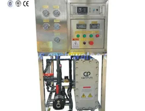
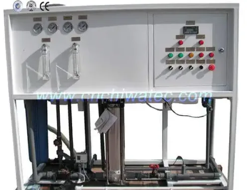
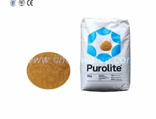
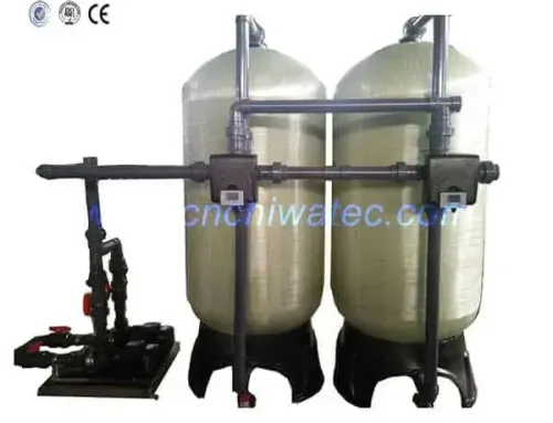
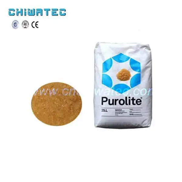
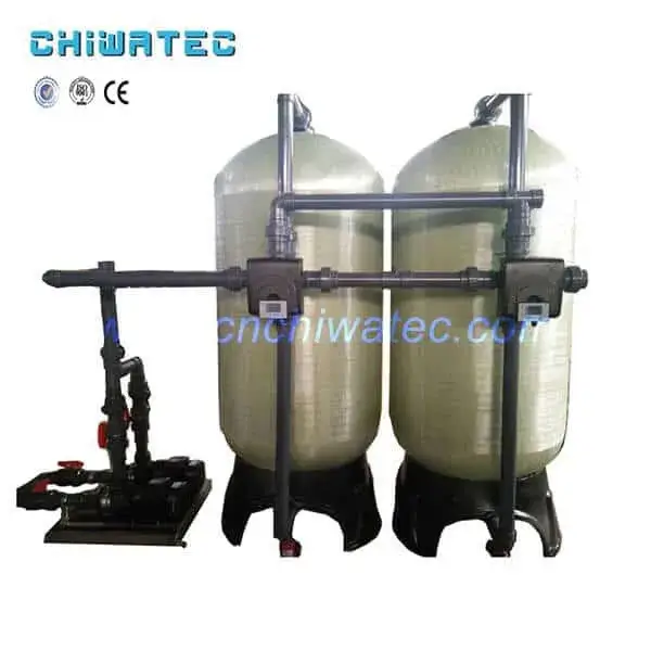
Ultrapure water equipment for the electronics industry consists of a comprehensive pretreatment system followed by a primary purification system and final polishing stage. The pretreatment system typically includes: a multi-media filter for removing suspended solids down to 10-25 microns, an activated carbon filter for removing chlorine, organic compounds, and taste/odor compounds, a sodium ion softener for hardness removal (< 0.5 ppm as CaCO3), and a precision (cartridge) filter (1-5 microns) as the final barrier before the RO membranes. All tanks (raw water, intermediate, RO permeate, and ultrapure water storage) are equipped with liquid level control systems for automated operation.
Automation and Monitoring
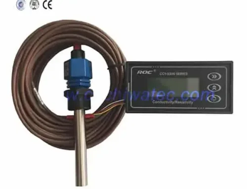
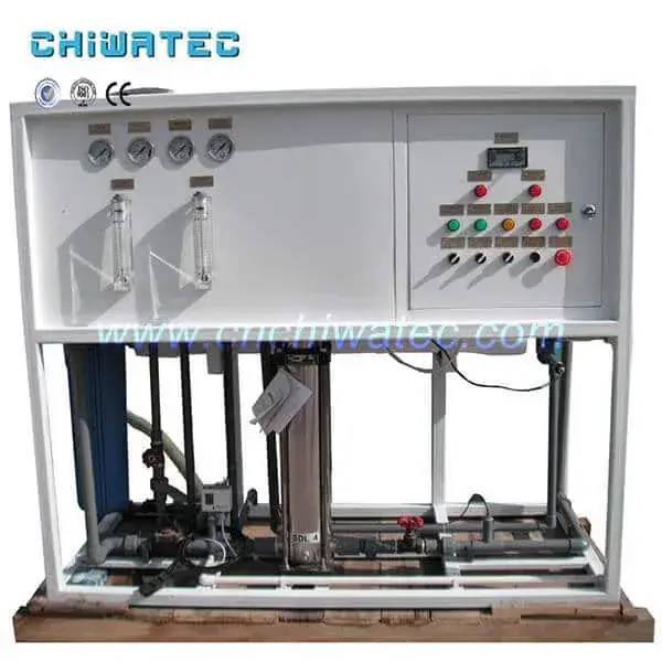
Modern electronics-grade UPW systems use PLC-based programmable controllers for fully unattended operation. High and low-pressure pumps are equipped with pressure protection devices. Online water quality monitoring instruments continuously measure resistivity, TOC, dissolved oxygen, particle counts, silica, and temperature. Data logging and alarm systems ensure immediate response to any quality deviation. CHIWATEC integrates these automation features into each custom-designed system to meet specific facility requirements.
2. What Is the Traditional Ion Exchange Process for Electronics Ultrapure Water?
Process Flow
The traditional method uses ion exchange resin to prepare ultrapure water without RO pretreatment. The basic process flow is: raw water to multi-media filter to activated carbon filter to precision filter to intermediate water tank to positive bed (cation exchanger) to negative bed (anion exchanger) to mixed bed (multi-bed) to ultrapure water tank to UPW pump to post-security filter to distribution point.
Limitations of the Traditional Approach
While this method can achieve the required water quality, it has significant drawbacks: high chemical consumption (acid for cation regeneration, caustic for anion regeneration), large volumes of acidic and alkaline wastewater requiring neutralization, inconsistent water quality between regeneration cycles, and frequent operator intervention for regeneration scheduling. These limitations make the traditional ion exchange-only approach economically and environmentally unsustainable for modern high-volume electronics manufacturing.
3. What Is the RO + Ion Exchange Process for Electronics Ultrapure Water?
Process Flow
The addition of reverse osmosis (RO) before ion exchange dramatically improves system efficiency. The process flow is: raw water to multi-media filter to activated carbon filter to precision filter to intermediate water tank to reverse osmosis equipment to mixed bed (multi-bed) to ultrapure water tank to UPW pump to post-security filter to distribution point. The RO membrane removes 95-98% of dissolved ions, reducing the ion load on the downstream mixed bed by 90-95%.
Advantages Over Traditional Method
The RO + mixed bed configuration extends regeneration intervals from daily to weeks or months, reduces chemical consumption by 80-90%, produces less wastewater, and provides more consistent water quality. However, chemical regeneration is still required, and the system still produces chemical waste that must be neutralized before discharge. This configuration was the industry standard from the 1980s through the early 2000s.
4. What Is the RO + EDI Process — The Modern Standard?
Process Flow
The latest and most environmentally sustainable process uses reverse osmosis combined with electrodeionization (EDI). The basic process flow is: raw water to multi-media filter to activated carbon filter to precision filter to intermediate water tank to reverse osmosis equipment to electro-deionization (EDI) to ultrapure water tank to UPW pump to post-security filter to distribution point. This configuration eliminates chemical regeneration entirely.
Why RO + EDI Is the Industry Standard
The RO + EDI process offers: no chemical handling or storage, no acidic or alkaline wastewater, continuous operation with no regeneration shutdowns, stable water quality (10-18.2 MOhm-cm), fully automatic PLC control, lower operating costs (30-50% less than RO + mixed bed), and a smaller footprint without regeneration tanks and chemical storage areas. This is the preferred process for all new electronics industry ultrapure water installations worldwide.
5. What Are the Three Process Methods Compared?
Comparison Summary
| Parámetro | Ion Exchange Only | RO + Ion Exchange | RO + EDI (Modern) |
|---|---|---|---|
| Water quality | 10-18.2 MOhm-cm | 10-18.2 MOhm-cm | 10-18.2 MOhm-cm |
| Chemicals required | Acid + caustic | Acid + caustic (80% less) | None |
| Regeneration frequency | Daily | Weekly to monthly | Continuous (none needed) |
| Operating complexity | High | Moderate | Low |
| Waste discharge | High (acid + alkaline) | Moderate | Minimal (5-15% reject) |
| Operating cost | High | Moderate | Low |
| Footprint | Large | Moderate | Compact |
| Modern standard? | No (obsolete) | Legacy installations | Yes (industry standard) |
For new electronics manufacturing facilities, the RO + EDI process is strongly recommended. For existing installations using RO + mixed bed, retrofitting with EDI modules typically provides a return on investment within 1-3 years through chemical and labor savings alone.
6. What Are the Application Fields of Ultrapure Water in the Electronics Industry?
Semiconductor and Integrated Circuit Manufacturing
Ultrapure water is used extensively in wafer fabrication for: wafer rinsing and cleaning between process steps, chemical mechanical planarization (CMP) slurry dilution and post-CMP cleaning, wet etching and photoresist stripping bath preparation, and final wafer rinse before drying. Semiconductor-grade UPW must meet ASTM D5127 Type E-1.2 specifications, including resistivity of 18.2 MOhm-cm, TOC below 2 ppb, dissolved oxygen below 5 ppb, particles larger than 0.05 microns below 100 particles per liter, and bacteria below 1 CFU per 100 mL.
Printed Circuit Board (PCB) Manufacturing
PCB fabrication uses UPW for: through-hole plating bath preparation and rinsing, solder mask development and cleaning, final board rinsing before solderability testing, and high-density interconnect (HDI) board process water. PCB-grade ultrapure water typically requires resistivity above 10 MOhm-cm and TOC below 50 ppb.
Liquid Crystal Display (LCD) and Optoelectronic Products
LCD panel manufacturing requires ultrapure water for: glass substrate cleaning, color filter production, liquid crystal injection process, and final module assembly cleaning. The water quality requirements for LCD production are similar to semiconductor-grade UPW due to the sensitivity of thin-film transistor (TFT) arrays to ionic contamination.
Ultrapure Materials and Chemical Reagents
The production of ultra-pure chemical reagents and electronic-grade materials requires UPW as both a process ingredient and cleaning medium. Electronic-grade acids, etchants, and solvents are diluted with UPW to achieve the purity levels required for semiconductor and flat-panel display manufacturing.
Laboratory and Pilot Plant Applications
Electronics industry research laboratories and pilot plants use compact UPW systems for: materials characterization sample preparation, prototype device fabrication, and analytical instrument feed water (ICP-MS, HPLC, IC). These systems typically produce 0.5-10 m3/h of Type I (18.2 MOhm-cm) ultrapure water.
7. What Are the Key Design Considerations for Electronics UPW Systems?
Material Selection
All wetted materials in contact with ultrapure water must be carefully selected to prevent leaching and contamination. Standard materials include: PVDF (polyvinylidene fluoride) or PTFE for piping in high-purity sections, 316L stainless steel with electropolished surfaces for storage tanks and heat exchangers, EPDM or PTFE elastomers for seals and gaskets, and virgin polypropylene for filter housings and EDI module components. CHIWATEC specifies only UPW-compatible materials for all electronics industry water systems.
System Redundancy
Electronics manufacturing facilities cannot tolerate unscheduled water system downtime. Critical UPW systems typically include: N+1 RO membrane arrays, dual EDI modules with automatic failover, redundant online monitoring instruments, and backup power for control systems. Storage tanks sized for 2-4 hours of peak demand provide buffer capacity during maintenance.
8. How to Maintain an Electronics Industry Ultrapure Water System?
Routine Maintenance Schedule
Daily checks include: verifying product water resistivity, TOC, and particle counts; checking RO feed pressure, permeate flow, and rejection rate; monitoring EDI module voltage and current; and inspecting pretreatment system pressure differentials. Weekly tasks include: calibrating online instruments, checking chemical dosing levels (antiscalant, reducing agent), and logging system performance data.
Periodic Maintenance
RO membrane cleaning is typically required every 3-12 months, depending on feed water quality. EDI modules require chemical cleaning every 6-18 months. Activated carbon replacement is typically annual. Multi-media filter media should be inspected annually and replaced every 2-3 years. All maintenance activities should follow validated procedures to prevent contamination of the UPW system.
9. What Are the Common Challenges in Electronics UPW Systems?
Bacterial Contamination
Ultrapure water provides an oligotrophic environment where certain bacteria can survive and multiply. Routine sanitization using hot water (80 degrees C / 176 degrees F), UV sterilization (254 nm), or ozone dosing (20-50 ppb) is essential. Periodic hydrogen peroxide or peracetic acid sanitization of storage tanks and distribution loops is recommended every 3-6 months.
Silica Breakthrough
Silica (SiO2) is poorly rejected by RO membranes and can pass through EDI modules under certain conditions. Continuous monitoring with online silica analyzers (detection limit below 0.5 ppb) is essential. If silica breakthrough is detected, RO membrane replacement or addition of a second-pass RO system may be required.
10. How to Select the Right UPW System for Your Electronics Facility?
Water Quality Requirements Assessment
Determine the required water quality based on the specific manufacturing processes. Semiconductor fabrication requires the highest quality (ASTM D5127 Type E-1.2), while PCB and general electronics assembly may require less stringent specifications. Over-specifying increases capital and operating costs unnecessarily, while under-specifying risks production yield losses.
Flow Rate and Expansion Planning
Size the UPW system based on peak demand plus 20-30% safety margin. Consider planned production capacity expansions when selecting RO array and EDI module configurations. Modular system designs allow capacity increases by adding RO pressure vessels and EDI modules without replacing the entire system. CHIWATEC provides complete system sizing and design services tailored to your facility’s specific requirements, including turnkey installation, commissioning, and ongoing technical support.
Conclusión
Ultrapure water is a critical utility for the electronics industry, directly impacting production yields, product quality, and operational costs. From the traditional ion exchange approach through the modern RO + EDI process, the technology for producing electronics-grade ultrapure water has evolved to eliminate chemical handling, reduce operating costs, and deliver consistent 18.2 MOhm-cm water quality. By understanding the equipment features, process flows, application requirements, and selection criteria covered in this guide, electronics manufacturers can implement UPW systems that meet their specific quality requirements while optimizing total cost of ownership. Contact Xi’an CHIWATEC today at [email protected] o [email protected] to discuss your electronics industry ultrapure water system requirements.
Frequently Asked Questions
Q1: What is the best process for producing ultrapure water in the electronics industry?
The RO + EDI (reverse osmosis + electrodeionization) process is the current industry standard and the best choice for new installations. It eliminates chemical regeneration, operates continuously, produces minimal wastewater, and consistently achieves 18.2 MOhm-cm water quality. For existing RO + mixed bed installations, EDI retrofitting typically provides a payback period of 1-3 years.
Q2: What water quality does the semiconductor industry require?
Semiconductor fabrication requires ultrapure water meeting ASTM D5127 Type E-1.2 specifications: resistivity of 18.2 MOhm-cm (minimum 18.0), TOC below 2 ppb (target below 1 ppb for advanced nodes), dissolved oxygen below 5 ppb, particles larger than 0.05 microns below 100 per liter, silica below 0.5 ppb, and bacteria below 1 CFU per 100 mL.
Q3: How much ultrapure water does a semiconductor fab consume?
A typical advanced semiconductor fabrication facility consumes 4-8 million gallons (15,000-30,000 cubic meters) of ultrapure water per day. With water recycling systems, raw water intake can be reduced by 70-85%. Water represents approximately 5-10% of a fab’s total operating expenses.
Q4: What causes TOC spikes in ultrapure water systems?
TOC spikes can be caused by: RO membrane degradation allowing organic compound passage, activated carbon fines breakthrough, bacterial regrowth in distribution loops, leaching from incompatible piping materials, and ion exchange resin breakdown releasing organic compounds. Regular TOC monitoring (online analyzers with 0.1 ppb detection limits) is essential for early detection.
Q5: Can ultrapure water systems be retrofitted with EDI?
Yes, existing RO + mixed bed systems can be retrofitted with EDI modules to replace the mixed bed deionization step. The retrofit typically involves: removing the mixed bed vessels, installing EDI modules with DC rectifier and controls, and reconfiguring the piping and instrumentation. The RO system must provide feed water meeting EDI inlet specifications (conductivity below 20 microSiemens/cm).
Related Resources and Further Reading
- Process Flow of Semiconductor Ultrapure Water Equipment
- Process Flow of Ultrapure Water Equipment in Electronics Factory
- Technical Characteristics of LCD Ultrapure Water Equipment
- Introduction of Laboratory Ultrapure Water Equipment and Treatment Process
- Ultrapure Water Purification Systems for Electronics Industry
¿Tiene un proyecto de tratamiento de agua con el que podamos ayudar?
* Diseño, mecanizado, instalación, puesta en marcha, personalización y servicio integral