Mixed bed regeneration is a critical maintenance procedure in water treatment systems, ensuring consistent production of ultrapure water for power plants, semiconductor facilities, and pharmaceutical manufacturing. When alkali injection failure occurs during regeneration, it compromises resin performance, reduces cycle capacity, and risks downstream water quality.
Industry data from 2025 indicates that alkali dosing failures account for approximately 23% of mixed bed regeneration issues in industrial ion exchange systems. This comprehensive troubleshooting guide covers all root causes, diagnostic procedures, and proven solutions to restore optimal mixed bed regeneration performance.
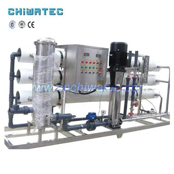
Understanding the alkali injection system components—including metering tanks, injectors, valves, and distribution piping—is essential for effective water treatment troubleshooting. This 2026 update incorporates latest field experiences, preventive maintenance recommendations, and industry best practices.
Root Cause Analysis: Why Alkali Cant Enter During Mixed Bed Regeneration
Mixed bed regeneration requires precise delivery of caustic soda (NaOH) solution to regenerate anion exchange resins. When alkali injection fails, multiple system components may be involved. Systematic diagnosis begins with understanding all potential failure points.
1. Alkali Metering Tank Level Problems
Low alkali level in the metering tank is the most common cause of injection failure. However, apparent low levels may stem from multiple issues:
- Actual low inventory: Caustic soda consumption exceeded replenishment schedule
- Level gauge malfunction: Float-type or sight glass indicators providing false readings
- Temperature effects: Caustic solution density changes affecting level indication
- Crystallization on sensor: Solid NaOH deposits interfering with level measurement
2025 Industry Statistics: Power plant surveys reveal that 34% of alkali injection failures trace to inaccurate level indication rather than actual supply depletion.
2. Valve Position and Actuation Failures
Proper valve sequencing is critical for mixed bed regeneration. Multiple valves must open in correct sequence:
- Alkali metering tank outlet valve: Must be fully open before regeneration cycle initiates
- Mixed bed alkali inlet valve: Controls caustic entry into the vessel
- Injector suction valve: Enables venturi effect for alkali draw
- Rinse and drain valves: Must be positioned correctly to establish flow path
Common failure modes:
- Pneumatic actuators losing air pressure (typically 4-7 bar required)
- Solenoid coil burnout preventing valve actuation
- Manual valves inadvertently left closed after maintenance
- Valve position switches failing to confirm open/closed status
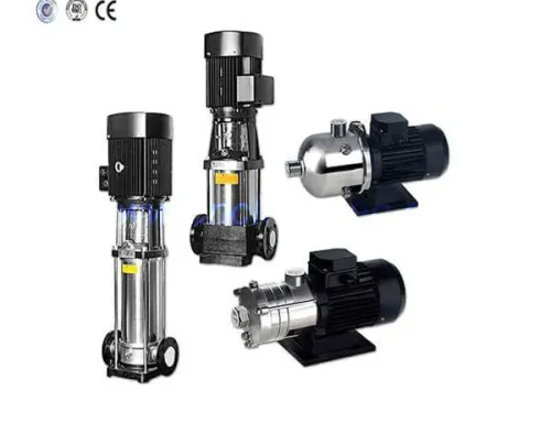
3. Alkali Injector Defects and Eductor Problems
los alkali injector (eductor/venturi) creates suction to draw caustic solution from the metering tank into the regeneration flow stream. Injector failures directly cause alkali injection failure:
Typical injector issues:
- Nozzle erosion: High-velocity water flow wearing throat diameter, reducing suction efficiency
- Throat blockage: Debris or crystallized salt obstructing flow passage
- Diffuser damage: Cracked or corroded diffuser preventing pressure recovery
- Incorrect motive pressure: Operating outside design range (typically 2.5-4.0 bar)
- Air leaks: Suction line leaks breaking vacuum, preventing alkali draw
Diagnostic tip: Disconnect injector suction line and observe if vacuum develops during operation. No vacuum indicates injector or motive water issues.
4. Alkali Pipeline Crystallization and Blockage
Caustic soda crystallization represents a severe and recurring challenge in water treatment systems. Sodium hydroxide solutions crystallize when:
- Temperature drops: 50% NaOH freezes at approximately 12°C (54°F); 32% NaOH at -18°C (0°F)
- Concentration exceeds solubility: Evaporation or water loss increasing concentration beyond saturation
- Stagnant conditions: Dead legs or low-flow sections allowing crystal nucleation
- Carbonation: Atmospheric CO₂ reacting with NaOH to form sodium carbonate precipitates
Field data (2025): Facilities in temperate climates report 3-5 crystallization incidents annually without heat tracing, versus near-zero with proper insulation and trace heating.
High-risk locations:
- Outdoor piping runs without insulation
- Valve stems and packing areas
- Strainer housings and filter bodies
- Injector suction connections
- Sample points and drain valves
5. Alkali Concentration Meter and Flow Instrument Faults
Modern ion exchange systems rely on instrumentation for regeneration control. Faulty instruments may prevent alkali injection or cause improper dosing:
Concentration meter issues:
- Conductivity sensor fouling: Caustic coating on electrodes causing drift or failure
- Temperature compensation errors: Incorrect readings due to failed RTD sensors
- Calibration drift: Sensors exceeding calibration interval (typically 30-90 days)
- Transmitter failure: 4-20mA signal loss triggering PLC interlocks
Flow meter problems:
- Magnetic flow meter electrode coating reducing accuracy
- Variable area flowmeter float sticking
- Pulse output failure on turbine meters
6. Nylon Mesh Sleeve and Branch Pipe Fouling
los alkali distribution system within the mixed bed vessel includes main headers, branch pipes, and retention elements (nylon mesh sleeves or wedge wire screens). Fouling restricts alkali flow:
Fouling mechanisms:
- Resin fines accumulation: Broken resin beads clogging mesh openings
- Iron oxide deposition: Rust particles from upstream piping adhering to mesh
- Organic fouling: Natural organic matter (NOM) coating distribution elements
- Biological growth: Bacteria or algae colonizing low-flow areas
- Crystalline deposits: Salt or carbonate scaling on mesh wires
Impact: Even 30-40% blockage of distribution sleeves can increase pressure drop sufficiently to prevent adequate alkali flow during regeneration.
Systematic Troubleshooting Procedures for Alkali Injection Failure
Effective water treatment troubleshooting requires a methodical approach. Follow this step-by-step diagnostic sequence to identify and resolve alkali injection failures efficiently.
Step 1: Verify Actual Alkali Tank Level
Dont rely solely on level indicators. Perform physical verification:
- Visual inspection: Open tank manway (with proper PPE—caustic burns are severe) and observe actual liquid level
- Sound the tank: Use a clean rod to measure liquid depth; compare with gauge reading
- Check concentration: Sample alkali solution and verify concentration (typically 30-50% NaOH)
- Inspect level gauge: Clean sight glass or verify float movement; replace if damaged
Corrective actions:
- Refill tank if level is genuinely low (maintain minimum 20% reserve)
- Calibrate or replace faulty level gauge
- Install redundant level switches for critical applications
Step 2: Confirm All Required Valves Are Open
Verify valve positions systematically:
- Review regeneration sequence: Consult system P&ID to identify all valves that must open during alkali injection step
- Check valve position indicators: Verify mechanical flags or PLC feedback show open status
- Manual verification: For critical valves, physically confirm position (handwheel position, actuator stem travel)
- Test actuator function: Cycle pneumatic or electric actuators to confirm full stroke
If valves wont open:
- Check instrument air pressure (minimum 4 bar required for most actuators)
- Verify solenoid valve energization (listen for click, check 24VDC signal)
- Inspect for mechanical binding (corroded stems, damaged seats)
- Contact maintenance for actuator repair or replacement
Step 3: Evaluate Alkali Injector Function
Injector testing requires isolating the component:
- Measure motive water pressure: Install gauge upstream of injector; verify 2.5-4.0 bar range
- Check motive water flow: Confirm adequate flow rate per injector specifications
- Test suction capability: Disconnect alkali suction line; place finger over suction port—should feel strong vacuum
- Inspect injector internals: Disassemble and examine nozzle, throat, and diffuser for wear or blockage
Injector maintenance guidelines:
- Clean or replace nozzles showing >10% diameter increase from erosion
- Remove all debris from throat section
- Replace cracked or corroded diffusers
- Verify gasket integrity on reassembly
Step 4: Address Alkali Pipeline Crystallization
Crystallized alkali requires careful remediation:
- Identify blockage location: Feel pipe temperature (cold spots indicate crystals); tap pipe (solid sound vs. hollow)
- Apply heat: Use steam tracing, heat guns, or warm water rags to melt crystals (wear face shield—crystals may eject)
- Flush with warm water: Once melted, flush line with 40-50°C water to remove residual solids
- Inspect and clean strainers: Remove and clean all inline strainers in alkali piping
Prevention strategies:
- Install heat tracing on all outdoor and unheated indoor piping
- Insulate pipes with 25-50mm closed-cell foam insulation
- Maintain minimum 10°C (50°F) ambient temperature in alkali storage areas
- Flush lines with dilute solution after each regeneration cycle
- Eliminate dead legs where solution can stagnate
Step 5: Verify and Calibrate Instruments
Instrument accuracy is essential for reliable mixed bed regeneration:
- Conductivity/concentration analyzer:
- Clean sensor with warm water and soft brush
- Perform two-point calibration using standard solutions
- Verify temperature compensation accuracy
- Flow meters:
- Zero-check magnetic flow meters
- Clean electrode surfaces if accessible
- Compare readings with portable ultrasonic flow meter
- Level transmitters:
- Verify against manual dip measurements
- Adjust zero and span as needed
Calibration frequency: Critical instruments should be calibrated every 30 days; others quarterly minimum.
Step 6: Clean Alkali Distribution Components
Distribution system cleaning may require vessel entry:
- Isolate and drain: Lock out/tag out mixed bed vessel; drain completely
- Access distribution headers: Remove manway; inspect main header and branch pipes
- Remove nylon mesh sleeves: Carefully extract sleeves for cleaning
- Clean mesh: Soak in warm water; use soft brush to remove debris (avoid wire brushes that damage mesh)
- Flush headers: Use high-pressure water jet to clear internal passages
- Reassemble and test: Reinstall sleeves; pressure-test before returning to service
Preventive maintenance: Inspect and clean distribution system every 12-18 months, or sooner if pressure drop increases significantly.
Prevention Strategies and Best Practices for Reliable Mixed Bed Regeneration
Preventing alkali injection failures is more cost-effective than reactive troubleshooting. Implement these best practices to ensure reliable mixed bed regeneration performance.
Design and Equipment Upgrades
2026 Recommended upgrades:
- Heat tracing: Install self-regulating heat trace cables on all alkali piping; maintain 15-20°C setpoint
- Redundant level measurement: Combine float switch with conductivity probe for reliable low-level alarm
- Quick-disconnect fittings: Enable rapid injector removal for maintenance without pipe cutting
- Transparent sight glasses: Install at key points to visually confirm alkali flow during regeneration
- Automated valve position feedback: Wire all actuators to PLC for real-time position monitoring
Preventive Maintenance Schedule
Weekly tasks:
- Verify alkali tank level (physical check, not just gauge)
- Inspect for visible leaks at valves and fittings
- Check instrument air pressure
Monthly tasks:
- Calibrate concentration analyzer
- Test valve actuation for all regeneration sequence valves
- Inspect injector suction line for air leaks
- Review regeneration data for anomalies (cycle time, alkali consumption)
Quarterly tasks:
- Disassemble and inspect alkali injector
- Clean or replace strainer elements
- Verify heat tracing operation (infrared thermometer scan)
- Test all level alarms and interlocks
Annual tasks:
- Open and inspect mixed bed vessel internals
- Clean or replace nylon mesh sleeves
- Flush alkali piping with warm water
- Comprehensive instrument calibration
Standard Operating Procedures (SOP)
Document and enforce these operational practices:
- Pre-regeneration checklist: Require operator sign-off on alkali level, valve positions, and instrument status before initiating regeneration
- Post-regeneration flush: Always flush alkali lines with dilute solution or water after each cycle
- Winter protocols: Increase inspection frequency during cold weather; verify heat tracing before freezing conditions
- Spare parts inventory: Maintain critical spares (injector nozzles, level gauge glasses, solenoid coils, mesh sleeves)
- Training: Annual hands-on training for all operators on alkali injection system components and troubleshooting
Safety: Handling Caustic Soda Safely
Personal Protective Equipment (PPE) requirements:
- Chemical splash goggles with side shields (ANSI Z87.1)
- Face shield for any procedure with splash risk
- Neoprene or nitrile gloves (minimum 14 mil thickness)
- Rubber apron or chemical-resistant suit
- Rubber boots (steel toe if handling drums)
Emergency procedures:
- Eyewash and safety shower must be within 10 seconds of alkali handling areas
- Neutralize skin contact with copious water (15 minutes minimum); seek medical attention
- Never add water to concentrated acid—always add acid to water (for neutralization)
- Maintain spill kit with absorbent pads and neutralizing agent (citric acid or vinegar solution)
Conclusion: Ensuring Reliable Mixed Bed Regeneration Performance
Alkali injection failure during mixed bed regeneration is a solvable problem with systematic diagnosis and proper preventive measures. By understanding the root causes—ranging from simple level gauge errors to complex distribution system fouling—operators can quickly restore water treatment system reliability.
Key takeaways for 2026:
- Prevention beats reaction: Implement robust preventive maintenance schedules to avoid unplanned downtime
- Crystallization is the enemy: Proper heat tracing and insulation eliminate most pipeline blockages
- Instruments need care: Regular calibration ensures accurate monitoring and control
- Training matters: Well-trained operators catch problems early, before they escalate
- Safety first: Always use proper PPE when handling caustic solutions
For complex alkali injection issues or mixed bed regeneration optimization, consult with tratamiento de aguas specialists who can provide on-site diagnostics and customized solutions.
Frequently Asked Questions (FAQ)
Q1: What is the most common cause of alkali injection failure?
A: Pipeline crystallization accounts for approximately 40% of alkali injection failures, especially in facilities without heat tracing. Low alkali tank level and valve position errors are the next most common causes.
Q2: How can I prevent caustic soda from crystallizing in pipes?
A: Install self-regulating heat trace cables maintaining 15-20°C, insulate all piping with 25-50mm closed-cell foam, eliminate dead legs, and flush lines with dilute solution after each regeneration cycle.
Q3: What concentration of NaOH should I use for mixed bed regeneration?
A: Typical regeneration uses 4-6% NaOH solution for anion resin. Storage concentration is usually 30-50%, diluted at the injector. Follow resin manufacturer specifications for optimal results.
Q4: How often should alkali injectors be inspected?
A: Quarterly inspection is recommended for critical applications. Disassemble, clean, and measure nozzle diameter. Replace if erosion exceeds 10% of original diameter.
Q5: What PPE is required when working with caustic soda?
A: Minimum requirements: chemical splash goggles, face shield, neoprene/nitrile gloves (14+ mil), rubber apron, and rubber boots. Eyewash and safety shower must be immediately accessible.
Q6: Why is my alkali concentration meter reading incorrectly?
A: Common causes include sensor fouling (caustic coating on electrodes), temperature compensation errors, or calibration drift. Clean sensor, verify temperature probe, and perform two-point calibration.
¿Tiene un proyecto de tratamiento de agua con el que podamos ayudar?
* Diseño, mecanizado, instalación, puesta en marcha, personalización y servicio integral