Multi-valve Controller in Water Treatment: Features, Functions, and Working Principle Guide (2026 updated)
A multi-valve controller is an essential automation component in water treatment systems that coordinates the opening and closing sequence of multiple diaphragm valves for processes such as filtration, softening, and ion exchange. This integrated control solution replaces manual valve operation with programmable automatic sequencing, significantly improving system reliability and operational efficiency. Xi’an CHIWATEC has been engineering multi-valve control systems for water treatment applications since 2012.
*Last Updated: March 2026
Why This Guide Matters
The global industrial process control market, which includes multi-valve controllers and automation systems for water treatment, was valued at approximately USD 68.3 billion in 2025 and is projected to reach USD 102.5 billion by 2035, growing at a CAGR of 4.1% (Allied Market Research, 2025). Water treatment facilities that adopt automated multi-valve control systems can reduce operator intervention by up to 70% and decrease valve maintenance costs by 35-50% compared to manually operated systems. Understanding the features, functions, and working principles of multi-valve controllers is critical for plant managers, maintenance engineers, and system designers seeking to optimize their water treatment operations.
Key Industry Trends (2026 Update)
- Smart controller integration: Modern multi-valve controllers now feature IoT connectivity, enabling remote monitoring and control via SCADA systems and mobile applications. Real-time status feedback reduces unplanned downtime by up to 40%.
- Energy-efficient diaphragm valve designs: New hydraulic and pneumatic diaphragm valves consume 25-35% less signal pressure energy, making multi-valve systems more sustainable for large-scale water treatment plants.
- Modular and scalable architectures: Controller manufacturers are adopting modular designs that allow facilities to expand from 8-step to 16-step programs without replacing the entire control system, reducing upgrade costs.
- Predictive maintenance algorithms: Multi-valve controllers with built-in cycle counting and wear analysis can predict diaphragm valve failure 2-3 weeks in advance, allowing proactive maintenance scheduling.
1. What Is a Multi-valve Controller in Water Treatment?
Definition and System Overview
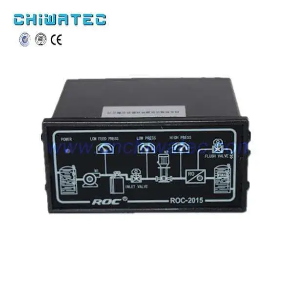
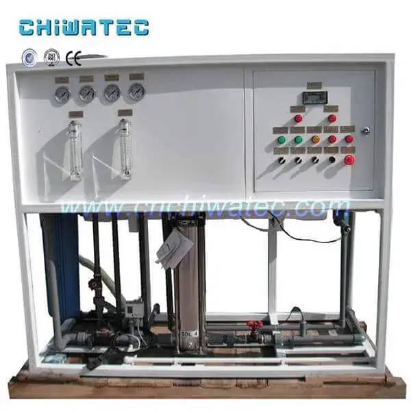
A multi-valve control system consists of a signal distributor and a time or flow program controller, enclosed in a waterproof controller housing. The signal distributor acts as a rotary guide valve that directs the opening and closing sequence of each diaphragm valve on the liquid or gas signal source switching equipment, completing automatic control of the entire water treatment system. This eliminates the need for individual solenoid valves for each control point, significantly reducing electrical complexity and potential failure points.
Typical Applications
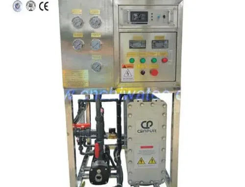
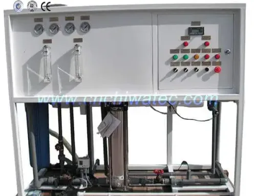
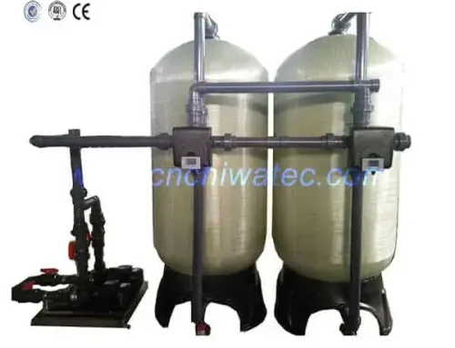
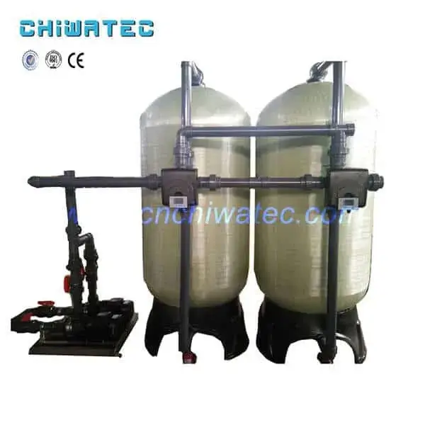
Multi-valve controllers are widely used in: water softening systems, multi-media filtration trains, activated carbon filtration, ion exchange deionization, chemical dosing systems, and backwash-controlled filtration processes. They can operate with 1.5-inch to 6-inch diaphragm valves and are compatible with tank diameters from 600 mm to 3,000 mm (24-120 inches), making them suitable for both small-scale and industrial water treatment installations.
2. What Are the Key Performance Characteristics of a Multi-valve Controller?
Signal Distributor Design
The spool of the signal distributor is manufactured from sturdy, corrosion-resistant, self-lubricating materials, providing long service life and maintenance-free operation. The distributor is driven by a small motor controlled by the time or flow programmer, or can be operated manually for commissioning and emergency operation. Turning the distributor to different positions opens or closes one or several channels simultaneously. The position number of each distributor channel corresponds to a specific system operation step, enabling precise process sequencing.
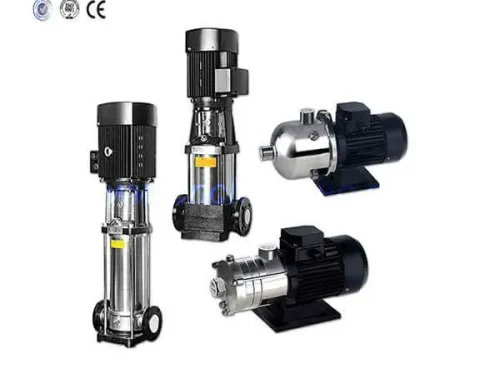
Diaphragm Valve Compatibility
The valves that perform the actual process operations are hydraulic or pneumatic diaphragm valves, widely used in domestic and international water treatment applications. These valves are cost-effective, easy to install, and simple to maintain. Professionals can perform inspection, maintenance, and replacement without specialized training. The signal pressure source for driving the diaphragm valves can be either liquid (hydraulic) or gas (pneumatic), providing installation flexibility. Since no continuous voltage is required unlike control solenoid valves, electrical breakdown and maintenance issues are greatly reduced.
3. What Functions Does a Multi-valve Controller Provide?
Core Automation Functions
- Set password protection prevents unauthorized parameter changes
- Perpetual calendar display for accurate time-based regeneration scheduling
- Regeneration step and time countdown display provides real-time process visibility
- External control signal chain control and step signal output enables integration with SCADA and plant-wide automation systems
- Five start modes: timed start, interval time start, remote transmission contact start (flow or analysis instrument), local temporary start, and local forced start
- Forced stepping start for on-site commissioning and troubleshooting
- Automatic origin position reset ensures consistent cycle starts
Programmability and Flexibility
The regenerative program can be configured with 1 to 8 steps, each adjustable from 5 to 9,999 seconds. This wide range accommodates various process requirements from rapid chemical dosing to slow media regeneration. The system status display provides real-time feedback on whether the system is in normal operation or regeneration mode. Power failure protection retains all set parameters for more than 3 years without battery backup, eliminating the need for reconfiguration after power outages.
Environmental Protection
The instrument housing is manufactured from engineering plastics with dustproof, corrosion-resistant, and waterproof sputtering protection. This allows installation in harsh water treatment environments, including chemical storage areas, outdoor pits, and high-humidity filter rooms.
4. How Does the Signal Distributor Work?
Rotary Distribution Principle
The signal distributor works on a rotary distribution principle. A small electric motor (controlled by the time or flow programmer) rotates the distributor spool to different angular positions. Each position opens specific channels while closing others. The open channels guide the signal pressure source to activate the corresponding diaphragm valves, while the closed channels drain the other diaphragm valves and return them to their normal (closed) positions.
Channel-to-Step Mapping
The number of distributor channels corresponds directly to the number of system operation steps. For example, a 6-channel distributor can control a 6-step regeneration cycle. Table mapping of channel positions to system steps allows operators to quickly identify which valve should be open at each stage of the process. Various combination designs of distributors and timers or flow sensors can meet the complex program control requirements of different water treatment systems, from simple softener regeneration to multi-step deionization processes.
5. What Are the Different Start Modes for Multi-valve Controllers?
Time-Based Start
Timed start mode initiates regeneration at preset intervals (e.g., every 24 hours, every 7 days) regardless of water volume processed. This is the simplest mode and works well for applications with consistent daily water consumption. Time-based regeneration typically uses 20-30% more water and regenerant chemicals but ensures system reliability without flow measurement equipment.
Flow-Based (Interval) Start
Interval time start mode triggers regeneration after a preset volume of water has passed through the system. This is more efficient than time-based start as regeneration only occurs when needed. A flow meter connected to the controller sends pulse signals that increment a counter — when the counter reaches the programmed value, regeneration initiates.
Remote and Manual Start
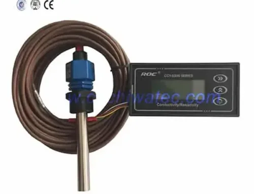
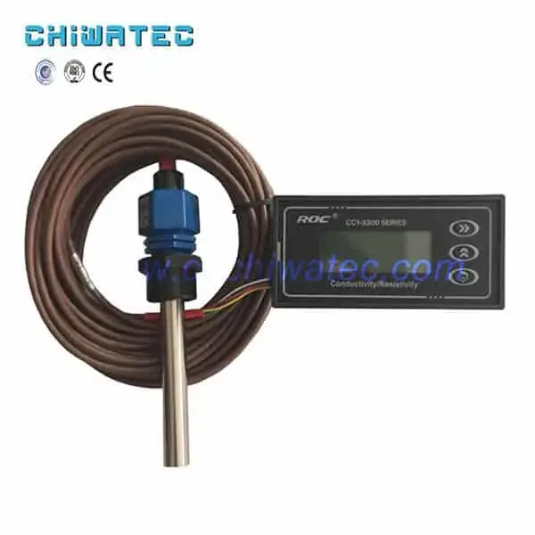
Remote transmission contact start allows external signals from a flow meter or water quality analyzer (such as a conductivity meter or hardness monitor) to trigger regeneration. Local temporary start enables maintenance personnel to initiate a regeneration cycle on demand, while local forced start is used for emergency operation when automated signals are unavailable.
6. How to Commission a Multi-valve Controller System?
Pre-Commissioning Checks
Before commissioning, verify that: all diaphragm valves are correctly connected to the signal distributor ports, the signal pressure source (liquid or gas) is available at the required pressure range (typically 0.2-0.6 MPa or 29-87 psi), the power supply matches the controller specifications, and all pipe connections are leak-free. Check the distributor rotation manually to ensure smooth operation through all positions.
Step-by-Step Commissioning
Commissioning involves: (1) connecting the signal pressure source to the distributor inlet, (2) programming the step sequence and timing parameters using the forced stepping mode, (3) manually rotating the distributor through each position to verify correct valve actuation, (4) checking that drain lines are properly connected for deactivated valves, (5) running a complete automatic cycle to verify sequence timing and valve operation, and (6) adjusting step timing as needed for optimal process performance.
7. What Is the Difference Between a Multi-valve Controller and a Single Multi-port Valve?
System Architecture
A multi-valve controller uses individual diaphragm valves for each process step, connected through a signal distributor. In contrast, a single multi-port valve (such as a Fleck or Autotrol valve) contains all flow paths within a single valve body. Multi-valve systems offer greater flexibility in valve sizing and placement, while multi-port valves offer a more compact footprint.
Advantages and Limitations
Multi-valve controllers: allow individual valve maintenance without system shutdown (with proper bypass arrangements), handle higher flow rates through large-diameter valves (up to 6 inches/150 mm), enable customized piping layouts, and are easier to upgrade or modify. They require more floor space and more pipe connections than multi-port valves.
8. How to Maintain a Multi-valve Control System?
Signal Distributor Maintenance
The signal distributor requires minimal maintenance due to its self-lubricating spool design. Periodically check for smooth rotation and inspect seals for wear. If rotation becomes stiff, clean the spool and housing with a mild solvent and apply food-grade lubricant to the sealing surfaces. The drive motor bearings should be inspected annually and replaced if noisy.
Diaphragm Valve Maintenance
Diaphragm valves require more frequent attention. Check diaphragms for cracking or deformation every 3-6 months, depending on operating frequency. Replace diaphragms at the first sign of leakage or stiff operation. The signal ports should be kept clean — debris in the signal lines can cause partial valve opening, leading to process inefficiency. CHIWATEC recommends maintaining a spare diaphragm kit for critical valves to minimize downtime.
9. What Are Common Troubleshooting Issues with Multi-valve Controllers?
Valve Not Actuating
If a specific diaphragm valve fails to open during its programmed step: check the signal pressure source pressure, verify the distributor channel alignment for that step, inspect the signal line for blockages or leaks, and confirm the diaphragm valve is not mechanically seized. Signal pressure below 0.15 MPa (22 psi) is the most common cause of incomplete valve actuation.
Incorrect Step Sequencing
If the controller advances through steps in the wrong order: check the distributor wiring to the motor, verify the origin position sensor (if equipped) is properly adjusted, and confirm the program settings are correct. For flow-based systems, verify the flow meter is sending consistent pulse signals.
Electrical Issues
Most electrical issues are related to power supply fluctuations or loose connections. The controller’s power failure protection retains parameters for over 3 years, so reprogramming is rarely needed after power restoration. Check fuses and terminal connections before replacing the controller board.
10. How to Select the Right Multi-valve Controller for Your Application?
Flow Rate and Valve Sizing
Select diaphragm valve sizes based on the maximum flow rate and allowable pressure drop. Valve sizes typically range from 1.5 to 6 inches (38-150 mm). For a given flow rate, undersized valves increase pressure drop and reduce system capacity, while oversized valves increase cost and may operate unstably at low flow. de CHIWATEC engineering team can help match valve sizes to your specific flow and tank specifications.
Control Mode Requirements
Choose between time-based and flow-based control based on your water consumption pattern. Time-based controllers are sufficient for applications with predictable daily usage (municipal softening, filtration). Flow-based controllers are recommended for variable-demand applications (industrial processes, irrigation) where regeneration efficiency directly impacts operating costs.
Integration with Existing Systems
Ensure the multi-valve controller supports the required signal interfaces: dry contact, 4-20 mA, Modbus RTU, or pulse input for flow meters. If integration with a plant-wide SCADA system is planned, verify the controller provides external step signal output and remote start inputs.
Conclusión
Multi-valve controllers are a reliable, cost-effective automation solution for water treatment processes requiring sequenced valve operation. Their simple mechanical design, low maintenance requirements, and compatibility with standard diaphragm valves make them an excellent choice for water softening, filtration, and ion exchange applications. By understanding the features, functions, and working principles covered in this guide, water treatment professionals can select, commission, and maintain multi-valve control systems that deliver years of trouble-free operation. Contact Xi’an CHIWATEC today at [email protected] o [email protected] to discuss your multi-valve controller requirements and system design needs.
Frequently Asked Questions
Q1: What signal pressure is required for multi-valve controller operation?
The typical signal pressure range for hydraulic or pneumatic diaphragm valves is 0.2-0.6 MPa (29-87 psi). Minimum pressure for reliable valve actuation is approximately 0.15 MPa (22 psi). The signal source can be either liquid (hydraulic) or gas (pneumatic), chosen based on site availability and application requirements.
Q2: How many steps can a multi-valve controller handle?
Standard multi-valve controllers support 1 to 8 programmable steps, each adjustable from 5 to 9,999 seconds. Some advanced controllers support up to 16 steps. The number of available steps corresponds to the number of distributor channel positions, which can be customized for specific process requirements.
Q3: Can a multi-valve controller work with existing solenoid valves?
Multi-valve controllers are designed specifically for hydraulic or pneumatic diaphragm valves. They are not directly compatible with electric solenoid valves unless a pneumatic solenoid valve manifold (pilot-operated) is installed as an interface. However, the multi-valve approach is intended to replace multiple solenoid valves with a single distributor-driven system.
Q4: How long does the power failure protection last?
The power failure protection function retains all programmed parameters for more than 3 years without external power. This is achieved through non-volatile memory storage, eliminating the need for backup batteries or reprogramming after power outages. Upon power restoration, the controller resumes operation from the programmed step sequence.
Q5: What maintenance is required for the signal distributor?
The signal distributor is designed for maintenance-free operation due to its self-lubricating spool material. However, annual inspection of the spool for wear, cleaning of the housing interior, and verification of smooth rotation are recommended. The drive motor bearings should be checked annually and replaced if noise or resistance is detected.
Related Resources and Further Reading
- FLECK Centralized Control Valve: Performance Characteristics and Selection Guide 2026
- Fully Automatic Softened Water Equipment Controller: Product Features and Applications
- Introduction of Fleck Automatic Water Softener 2850 Multi-way Control Valve
- Selection and Application Range of FLECK Softened Water Equipment
- Water Treatment Control Valves and Accessories
¿Tiene un proyecto de tratamiento de agua con el que podamos ayudar?
* Diseño, mecanizado, instalación, puesta en marcha, personalización y servicio integral