RO Membrane Performance FAQ: Common Questions About Silicon, pH, TDS, and Contamination 2026
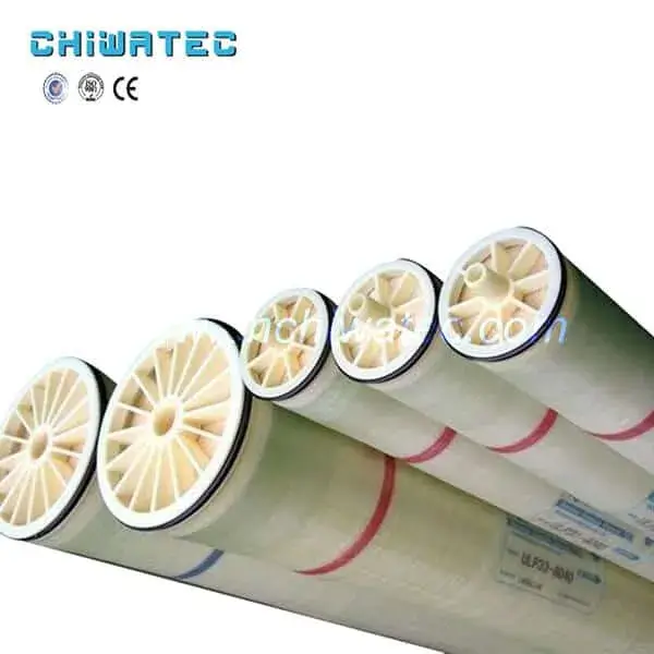
Understanding the factors that affect RO membrane performance — including feed water chemistry, silicon speciation, pH effects, and contamination indicators — is essential for system optimization. This RO membrane performance FAQ addresses key questions about microorganism removal, RO vs ion exchange selection, silicon removal, pH impact on rejection, TDS-conductivity relationships, and contamination detection. CHIWATEC supplies high-performance RO membranes and complete reverse osmosis systems engineered for reliable and efficient water treatment.
RO Membrane Performance FAQ: Capabilities and Technology Comparison
21. Can reverse osmosis remove microorganisms such as viruses and bacteria?
Yes, reverse osmosis membranes have an exceptionally dense active layer with a pore size of approximately 0.1-1 nm, achieving a removal rate of at least 3 log (99.9%) for viruses, phages, and bacteria. The removal mechanism is primarily size exclusion — microorganisms are physically retained on the feed side while water molecules pass through. However, it is critical to note that microorganisms can still colonize the permeate side if the system has inadequate seals, damaged O-rings, or compromised brine seals that allow feed water to bypass the membrane. The water produced on the permeate side of a healthy membrane is essentially sterile at the point of production, but post-membrane contamination is possible. Therefore, the system’s microbiological safety depends on proper design (including intact brine seals and O-rings), regular monitoring (conductivity and bacterial testing), and maintenance. For drinking water applications, RO is often combined with UV disinfection downstream as a final barrier against any post-membrane contamination.
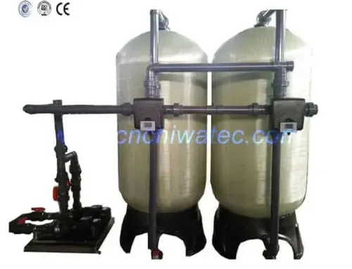
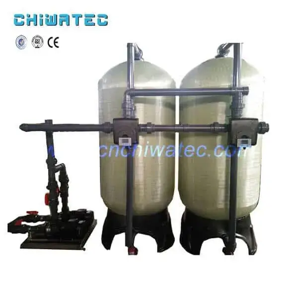
22. Should I use reverse osmosis or ion exchange for general feed water treatment?
The choice between RO and ion exchange (IX) depends primarily on feed water TDS and the required product water quality. As a general economic guideline:
| Feed Water TDS | Recommended Process | Typical Operating Cost |
|---|---|---|
| < 500 mg/L | Ion exchange may be more economical for low-to-moderate flow rates | $0.10-0.30/m³ |
| 500-3,000 mg/L | RO is typically more economical; IX polishing may follow | $0.20-0.50/m³ (RO) |
| > 3,000 mg/L | RO is significantly more economical; IX for polishing | $0.30-0.80/m³ (RO) |
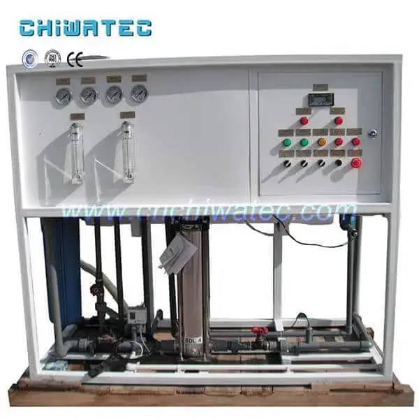
Modern water treatment plants commonly use a hybrid RO+IX configuration — RO removes 95-99% of dissolved solids, then a downstream mixed-bed ion exchanger polishes the RO permeate to achieve ultrapure water quality (18.2 MΩ·cm resistivity). This combined approach is more cost-effective than IX alone for high-TDS feed water because RO handles the bulk desalination load, reducing chemical regeneration frequency for the IX system by 90-95%. For low-TDS feed water (< 500 mg/L), IX alone may be competitive, but RO+IX remains the preferred configuration for ultrapure water applications in pharmaceutical, power generation, and electronics industries.
Water Chemistry: Silicon, pH, and TDS Effects on RO Performance
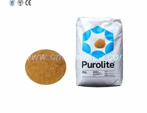
23. How can silicon be removed from water in RO systems?
Silicon in water exists in two forms — active silicon (monomeric silicic acid, H₄SiO₄, < 1 nm in size) and colloidal silicon (polymerized silica, 5-100 nm). These forms require different removal strategies:
- Colloidal silicon: Can be removed by fine physical filtration processes including reverse osmosis (90-99% rejection as part of particulate filtration), ultrafiltration, and coagulation clarification (using alum or ferric chloride). Techniques relying on ionic charge separation — ion exchange resins and continuous electrodeionization (CEDI) — have very limited effectiveness for colloidal silicon because it lacks ionic charge characteristics.
- Active silicon (reactive silica): Much smaller than colloidal silicon, active silicon cannot be removed by conventional filtration, clarification, or air flotation. Effective removal processes include reverse osmosis (90-97% rejection depending on pH — higher rejection at pH > 8 due to silicic acid ionization), strong base anion exchange resins (Type II preferred for silica), and continuous electrodeionization (CEDI).
For feed water with total silica exceeding 30 mg/L, silica scale prevention is critical. RO design should limit concentrate silica concentration to below 100 mg/L (without antiscalant) or below 240 mg/L (with specialized silica antiscalant). Operating at higher temperature and pH above 8.0 increases silica solubility, reducing scaling risk.
24. What effect does pH have on RO membrane rejection, water production, and membrane life?
The operating pH range for standard polyamide RO membranes is 2-11 (continuous) and 1-12 (cleaning). pH has minimal direct effect on the membrane polymer itself — this is a key advantage of RO over other membrane types. However, pH dramatically affects the rejection of certain ions through its influence on ionization state:
- Weak acids (e.g., silicic acid, boric acid, citric acid): At low pH, these compounds exist in non-ionized (uncharged) form and pass through the membrane more easily, reducing rejection. At high pH, they dissociate into charged ions that are effectively rejected by the membrane. For example, boron rejection increases from approximately 40% at pH 7 to 90% at pH 10 due to borate ion formation.
- Dissolved gases (CO₂, H₂S, NH₃): At low pH, gases are uncharged and pass through the membrane. At high pH, they ionize and are rejected. This principle is used in multi-pass RO systems with pH adjustment between passes for high-purity water production.
- Net water production: pH does not significantly affect membrane water permeability within the normal operating range. The small flux changes observed with pH variation are primarily due to osmotic pressure changes from different ion rejection patterns.
Membrane life is not directly affected by pH within the specified operating range, but extreme pH excursions during cleaning (below pH 1 or above pH 12) can accelerate membrane hydrolysis and reduce service life.
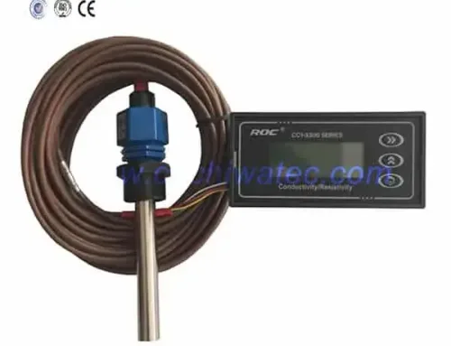
25. What is the relationship between feed water TDS and conductivity?
Total Dissolved Solids (TDS) and conductivity are directly related in most natural waters. The conversion factor (k = TDS/conductivity) varies based on the ionic composition:
| Water Type | Typical TDS/Conductivity Ratio |
|---|---|
| Agua de mar | 1.4 (TDS in mg/L = 1.4 × EC in μS/cm) |
| Brackish water | 1.3 |
| Superficie del agua | 1.2-1.5 |
| Groundwater | 1.3-1.7 |
| Sodium chloride dominant | 1.5-1.7 |
| Sulfate or bicarbonate dominant | 1.2-1.4 |
For RO system design, the conversion factor is used to input TDS values into projection software (ROSA, IMSDesign, etc.) when only conductivity data is available. The standard approximation: TDS (mg/L) ≈ 0.64 × Conductivity (μS/cm). For accurate results, direct TDS measurement or gravimetric analysis is recommended for site-specific calibration.
Troubleshooting RO Membrane Contamination
26. How can you tell if the RO membrane has been contaminated?
Membrane contamination can be identified through several observable symptoms that affect system operating parameters:
- Permeate flow decline: Normalized permeate flow drops below baseline at constant pressure and temperature. A 10-15% drop indicates cleaning is needed.
- Increased operating pressure: To maintain constant permeate production, the feed pressure must be increased beyond the initial design value by 10-15% or more.
- Increased pressure drop (ΔP): The pressure difference between feed and concentrate increases by 15-20% above baseline, indicating fouling in the feed channel.
- Membrane element weight increase: When removed from the pressure vessel, fouled elements weigh significantly more due to accumulated foulants (scale, biofilm, or particulate matter).
- Salt rejection changes: Depending on the foulant type, rejection may either increase (scale forming a secondary barrier) or decrease (biofilm or organic fouling damaging the active layer).
- Water channel blockage test: When a membrane element is removed vertically and water is poured onto the feed end face, water should flow through the element. If water overflows the end face without penetrating, the feed channels are completely blocked — indicating severe contamination requiring replacement rather than cleaning.
Regular logging of normalized performance parameters allows early detection before contamination becomes severe. Daily monitoring of normalized permeate flow, salt passage, and ΔP is recommended for all RO systems.
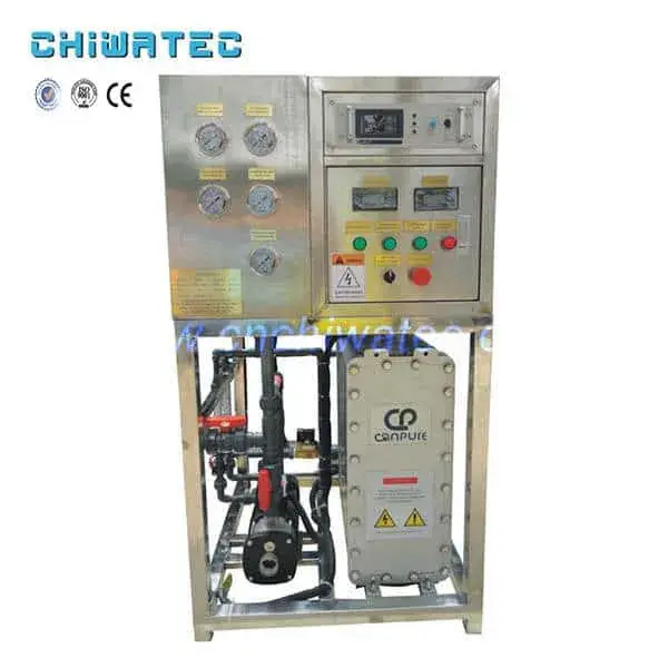
30. When should the RO membrane system be performance-tested and how?
Performance testing of the RO system should be conducted in three scenarios:
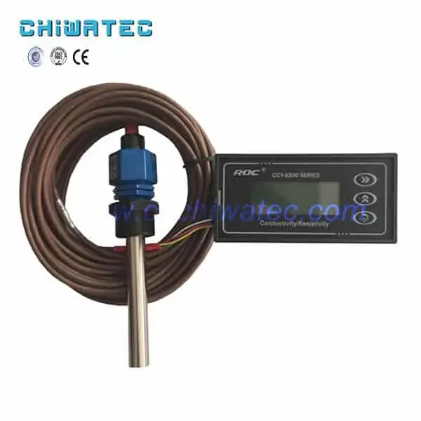
- Routine monitoring (daily): Track overall system parameters — feed pressure, permeate flow, concentrate flow, conductivity, temperature, and calculated normalized values. A sudden change in any parameter warrants investigation.
- Troubleshooting (when performance declines): Measure the TDS of permeate from individual pressure vessels to identify which vessels contain compromised elements. Use a conductivity probe with a flow cell at each vessel’s permeate sample port.
- Element-level diagnosis (when vessel-level data is inconclusive): The standard procedure involves removing suspect membrane elements and performing a vacuum test (for O-ring integrity), a reverse pressure test (for seal damage), or a probe test along the permeate tube to identify internal leakage points. Individual element testing in a test skid under standard conditions (2,000 mg/L NaCl, 15.5 bar, 25°C, pH 6.5-7.0, 15% recovery) provides the most accurate assessment of element health.
A comprehensive membrane autopsy — including visual inspection, loss-on-ignition analysis, scanning electron microscopy (SEM), and energy-dispersive X-ray spectroscopy (EDS) — should be performed on sacrificial elements from problem systems to identify foulant composition and guide pretreatment upgrades.
Energy-Efficient Membrane Selection
27. When should low-energy or ultra-low-energy RO membrane elements be selected?
Low-energy (LE, LP) and ultra-low-energy (XLE) membrane elements are designed for applications where minimizing energy consumption is the primary objective, even at the expense of slightly reduced salt rejection. Key selection criteria:
- Low-energy membranes (LE/LP): These elements operate at 8-10 bar compared to 12-15 bar for standard brackish water membranes, reducing specific energy consumption by 15-25%. They achieve 98-99% salt rejection — suitable for most industrial and commercial applications where product water TDS below 100 mg/L is acceptable.
- Ultra-low-energy membranes (XLE): These operate at just 5-7 bar — approximately 50% of the energy consumption of standard BW30 elements. However, salt rejection is lower at 95-97%. XLE elements are ideal for applications where moderate water quality is acceptable and energy cost is a major concern, such as agricultural irrigation, cooling tower makeup, and low-pressure boiler feed.
Select low-energy elements when: (1) energy costs are above $0.10/kWh, (2) feed water TDS is below 2,000 mg/L, (3) product water quality requirements are moderate, and (4) the system operates 16-24 hours per day. For high-rejection requirements (salt passage < 0.5%), standard membrane elements remain the preferred choice. A life-cycle cost analysis comparing higher capital cost (more elements to achieve the same production at lower pressure) vs. operating savings should be conducted before specification.
Frequently Asked Questions (FAQ)
Can RO membranes remove dissolved gases?
No. RO membranes cannot effectively remove dissolved gases such as CO₂, H₂S, NH₃, and O₂ because gas molecules are small and uncharged. A degasification tower or membrane contactor is required after RO for gas removal.
How does feed water temperature affect RO membrane salt rejection?
Salt rejection decreases slightly as temperature increases — typically by 0.1-0.2% per °C. This occurs because higher temperature increases the polymer chain mobility in the membrane active layer, allowing slightly more salt passage. The effect is minor compared to the flux increase.
What is the typical lifespan of an RO membrane before replacement?
With proper pretreatment and operation, thin-film composite RO membranes typically last 3-7 years. Factors that reduce lifespan include: chlorine exposure, high operating pressure, frequent cleaning, and challenging feed water quality. Annual membrane autopsy helps predict end-of-life timing.
Conclusion & Call to Action
This RO membrane performance FAQ covers critical topics affecting RO system output quality and reliability — from microorganism removal and RO vs IX selection to silicon chemistry, pH effects, TDS measurement, and contamination diagnosis. Understanding these fundamentals helps operators optimize system performance and extend membrane service life. CHIWATEC supplies a full range of RO membranes, antiscalants, cleaning chemicals, and complete system design services. Contact our engineering team for technical support, membrane selection assistance, or system performance evaluation. Email us at [email protected] o [email protected] for expert assistance.
Related Resources and Further Reading
- Reverse Osmosis Membrane Advantages: Complete Guide to RO Membrane Benefits, Performance, and Applications
- RO Membrane Chemical Cleaning: Complete Guide to Fouling Analysis and CIP Technology 2026
- RO Membrane Pollution and Cleaning Tips: Complete Guide 2026
- RO Membrane Fouling and Cleaning Guide 2026: Identify Pollutants and Restore Performance
- RO Water Treatment Systems and Membrane Products — View Our Complete Range
¿Tiene un proyecto de tratamiento de agua con el que podamos ayudar?
* Diseño, mecanizado, instalación, puesta en marcha, personalización y servicio integral